Bionic tire structure

A tire and carcass layer technology, which is applied to tire parts, reinforcing layers of pneumatic tires, transportation and packaging, etc., can solve the problems of increasing tire life, increasing tire production price, increasing tire rolling resistance, etc. Deformation, reduce the probability of damage, reduce the effect of displacement and deformation

Inactive Publication Date: 2015-09-02
JIANGSU UNIV
View PDF13 Cites 2 Cited by
  • Summary
  • Abstract
  • Description
  • Claims
  • Application Information

AI Technical Summary

Problems solved by technology

[0003] Chinese patent CN102114754 improves the durability performance of tires by mixing aramid pulp into the belt layer compound. However, this method needs to adjust the tire compound, and the cost is high and the implementation is cumbersome; The rubber blocks are arranged between the belt layers to reduce the phenomenon of gas accumulation at the edge of the belt layer to increase the life of the tire. However, this method requires the design of a special molding machine, which is complicated to design and manufacture; Chinese patent CN203818934 uses a wrapped steel wire to carry out belting on the shoulder of the tire. layer reinforcement to achieve the purpose of improving tire performance, but this method will lead to an increase in tire mass, resulting in increased tire rolling resistance; Chinese patent CN1775568A reduces the number one belt by adding edge strips and reinforcing materials at the end of the belt layer The edges of the belt are separated. However, this patent structure is complex and cumbersome to form, and there is little consideration for the second belt layer with the highest strain energy density of the tire, so it is difficult to be used in engineering practice.
Therefore, there is currently no effective way to increase the tire life without increasing the tire production price and reducing the tire production efficiency under the condition of slightly modifying the existing tire manufacturing equipment.

Method used


Image

  • Bionic tire structure
  • Bionic tire structure
  • Bionic tire structure

Examples


Embodiment Construction

[0017] The present invention will be further described below in conjunction with the accompanying drawings and specific embodiments, but the protection scope of the present invention is not limited thereto.

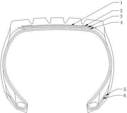
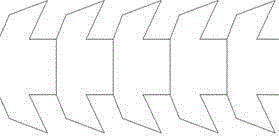
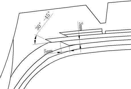
[0018] Such as figure 1 As shown, a bionic structure tire includes the first belt layer 4, the second belt layer 3, the third belt layer 1, the zeroth belt layer 2, the reinforcing layer 5 and the carcass layer 6 ; The zeroth belt layer 2 includes the left zeroth belt layer and the right zeroth belt layer, and the left zeroth belt layer and the right zeroth belt layer are symmetrically arranged on the third The left and right sides of the belt layer 1; the first belt layer 4 and the second belt layer 3 imitate the spine structure of snakes, and the left and right sides of the first belt layer 4 and the second belt layer 3 Both ends are of wedge-shaped structure, the left end surface of the left No. 0 belt layer is a wedge-shaped structure, and the right end surface of t...


PUM


Abstract

The invention discloses a bionic tire structure. The bonding mechanism of the vertebra and tenon of a snake is integrated and grafted into the end part of a belt ply of a tire, so that each belt ply forms a certain bevel angle and an interlamination difference along the horizontal and axial direction, the stress concentration on the should of the tire is improved and the stress between the belt ply and the tread rubber material is uniformly distributed. According to the belt ply structure of the tire, on the basis that an existing tire structure is only slightly modified, the bonding strength between belt ply and the tread rubber is enhanced; the occurrence that the edge part of the belt ply is likely to be displaced and deform during vulcanization later is reduced; the occurrences that the shoulder of the tire is cracked and the tire comes into burst due to overheat are reduced; the quality of the tire is greatly improved and the service life of the tire is greatly prolonged; The invention is also suitable for the design of the reverse wrapping end part of the tire; by arranging the bionic tire structure at the end parts of a reinforced layer and a carcass, the stress concentration at the bead of the tire can be remarkably reduced.

Description

technical field [0001] The invention relates to tire structure design, in particular to a bionic tire structure. Background technique [0002] During the tire manufacturing process, the end of the belt layer and the turn-up end of each layer are the main areas of stress concentration, and the shoulder and ring cracks of the tire are the main types of tire damage, basically the end of the belt layer and the turn-up end. Therefore, reducing stress concentration is a problem that must be faced in tire structure design. [0003] Chinese patent CN102114754 improves the durability performance of tires by mixing aramid pulp into the belt layer compound. However, this method needs to adjust the tire compound, and the cost is high and the implementation is cumbersome; The rubber blocks are arranged between the belt layers to reduce the phenomenon of gas accumulation at the edge of the belt layer to increase the life of the tire. However, this method requires the design of a special ...

Claims


Application Information

Patent Timeline
Patent Type & Authority Applications(China)
IPC IPC(8): B60C9/24B60C9/18
Inventor 王国林孙砚田周浩魏新龙付晶
Owner JIANGSU UNIV
Why Eureka
Try Eureka