Direct-driven elevator system

An elevator system, direct drive technology, applied in propulsion systems, elevators in buildings, electrical components, etc., can solve problems such as excessive self-weight, unreasonable force, and difficulty in ensuring the long-distance working air gap of direct drive elevators, etc. Achieve the effects of less quantity, less pressure, lower motor material and processing costs

Active Publication Date: 2015-09-02
JIAOZUO HUAYING ELECTROMECHANICAL TECH
View PDF8 Cites 23 Cited by
  • Summary
  • Abstract
  • Description
  • Claims
  • Application Information

AI Technical Summary

Problems solved by technology

[0005] The technical problem to be solved by the present invention is that it is difficult to guarantee the long-distance working air gap of the direct-drive elevator, the operating mode of the main body and the unreasonable force, excessive self-weight and other engineering problems. It provides a simple structure, reliable positioning, braking and operation, dynamic Light weight, reasonable main force, excellent performance, suitable for long-distance direct-drive elevator drive

Method used


Image

  • Direct-driven elevator system
  • Direct-driven elevator system
  • Direct-driven elevator system

Examples


Embodiment 1

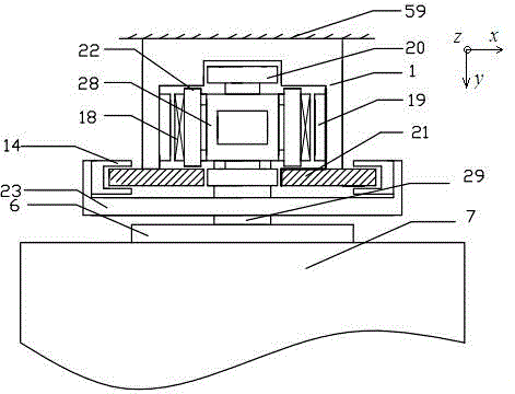
[0031] Such as figure 1 As shown, in this description, the normal direction of the linear motor is defined as the X-axis coordinate direction, also known as the left-right direction or the left and right sides; the movement direction is defined as the Z-axis direction, also known as the up-down direction or the upper end and the lower end ; The direction perpendicular to the XZ plane is defined as the Y-axis direction, also known as the front-back direction.

[0032] The direct-drive elevator system of the present invention includes a U-shaped support assembly 1, a linear motor mover 18, a linear motor stator 19, a brake guide rail 21, a brake 14, a safety gear, a mover frame 28, and an air gap guide wheel Group 20, front and rear anti-tilt wheel groups 22, U-shaped frame II 23, car frame 6 and main coupling shaft 29.

[0033] The U-shaped support assembly 1 is installed on the elevator shaft wall 59, and the linear motor stator 19 is relatively arranged on the two parallel s...

Embodiment 2

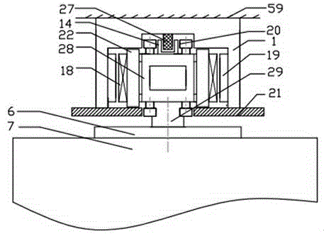
[0043] Such as figure 2 As shown, the air gap guide wheel set 20 is arranged on the front and rear sides of the mover frame 28, and the positioning wheel 1 of the air gap guide wheel set 20 is composed of two parallel small wheels, and these two small wheels are connected with the U-shaped support assembly respectively. The left and right side walls of the bar-shaped groove forming the positive side of 1 are in rolling contact. The positioning wheel II of the air gap guide wheel set 20 is composed of two parallel small wheels, and these two small wheels are respectively in rolling contact with the transverse inner end surfaces of the two rows of brake guide rails 21, and the air gap guide wheel set 20 is used to ensure the straight line. The air gap between the motor stator 19 and the linear motor mover 18.

[0044] A bar-shaped brake rail 27 is set in the center of the bar-shaped groove on the front side of the U-shaped support assembly 1, and the brake rail 27 cooperates w...

Embodiment 3

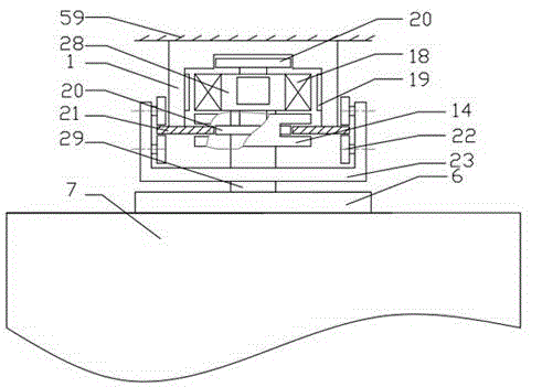
[0047] Such as image 3 As shown, the brake 14 is arranged on the front side of the mover frame 28 and cooperates with the brake guide rail 21 .

[0048] The front and rear anti-tilt wheel sets 22 are symmetrically arranged on the left and right ends of the U-shaped frame II 23, and the left support wheel set of the front and rear anti-tilt wheel sets 22 is composed of two parallel small wheels, and these two small wheels are connected with the left end of the guide rail 21 respectively. The front and rear sides are in rolling contact, and correspondingly, the right support wheel set of the front and rear anti-tilt wheel set 22 is formed by two parallel small wheels, and these two small wheels are respectively in rolling contact with the front and rear sides of the right end of the guide rail 21 for Prevent the car from tipping over in the front and rear directions.

[0049] All the other structures are the same as in Example 1.


PUM


Abstract

The invention belongs to the field of wireless lifting and particularly relates to a direct-driven elevator system. The direct-driven elevator system comprises rotors connected with a lift car frame and stators fixed to a shaft wall of an elevator, wherein the stators are arranged at two opposite sides of a fixed U type supporting assembly, the number of the rotors is two, the two rotors are arranged in a back-to-back mode, and the stator and the rotor on each side form a linear motor to form a bilateral motor. The direct-driven elevator system adopts a bilateral motor simple structure, the rotors use a rectangular pipe structure rotor frame in common, meanwhile, the power driving and the positioning guiding braking are arranged in the U type supporting assembly in a centralized mode, a bilateral hybrid excitation linear motor can also be used as a lift power source and a magnetic levitation guiding device as well, the overall arrangement is more reasonable, the movement component can be made to be lightest, the machining, the installation and the maintenance are all very convenient, the practical degree is high, and the electromagnetic compatibility is good.

Description

technical field [0001] The invention belongs to the field of cordless lifting, and in particular relates to a direct drive elevator system. Background technique [0002] Linear motor is a new type of power machinery that can directly move linearly without intermediate transmission mechanism. It can be used in the lifting field to realize the ropeless lifting mode without wire rope and without lifting machine room, which can greatly increase the conveying capacity of the hoist or elevator. and delivery distance. This kind of cordless hoist or elevator mainly has two driving structure types: induction linear motor and linear synchronous motor. Among them, the permanent magnet linear synchronous motor has high force index, large working air gap and large thrust, and is recognized as the most suitable for cordless hoists. One of the driving sources. [0003] Over the years, people have carried out long-term exploration on the linear motor cordless elevator hoisting system, and...

Claims


Application Information

Patent Timeline
Patent Type & Authority Applications(China)
IPC IPC(8): B66B11/04H02K41/02H02K16/00H02K7/14
CPCB66B11/0407H02K16/02H02K41/031
Inventor 汪旭东许孝卓封海潮许宝玉
Owner JIAOZUO HUAYING ELECTROMECHANICAL TECH
Why Eureka
Try Eureka