Wallboard interlayer connection for use at bottom enhanced part of laminated shear wall structure

A technology of interstory connection and shear wall, applied in the direction of walls, building components, building structures, etc., can solve the problem of reducing structural deformation capacity and ductility, large concrete compressive strain, and composite slab concrete shear wall structure cannot fully achieve etc. to achieve the effect of increasing ductility and deformation capacity

Inactive Publication Date: 2015-09-02
HEFEI UNIV OF TECH
View PDF9 Cites 2 Cited by
  • Summary
  • Abstract
  • Description
  • Claims
  • Application Information

AI Technical Summary

Problems solved by technology

This swaying mechanism makes the deformation concentrated near the horizontal seam of the laminated wall panel, and the seismic energy is mainly dissipated through this part, resulting in a large tensile deformation of the vertical steel bars passing through the seam section, and even being broken , the compressive strain of the concrete in the compression zone is also relatively large, which reduces the deformation capacity and ductility of the structure to a certain extent
When the reinforced part of the bottom adopts laminated wall panels, the laminated slab concrete shear wall structure cannot fully achieve the purpose of "equivalent to cast-in-place"
When used in tall high-rise residential buildings, the horizontal joints between the shear wall and the foundation have a large opening width under rare earthquakes, and the deformation capacity of steel bars and concrete is difficult to meet the requirements

Method used


Image

  • Wallboard interlayer connection for use at bottom enhanced part of laminated shear wall structure
  • Wallboard interlayer connection for use at bottom enhanced part of laminated shear wall structure
  • Wallboard interlayer connection for use at bottom enhanced part of laminated shear wall structure

Examples


Embodiment Construction

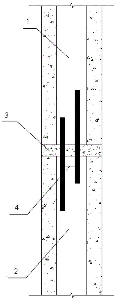
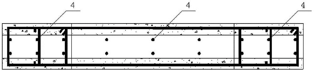
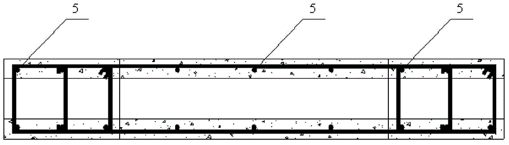
[0018] Such as Figure 1-Figure 3 As shown in the figure, the interlayer connection node of the reinforced part of a laminated slab shear wall structure includes the upper and lower laminated wallboards 1 and 2, and the upper and lower laminated wallboards 1 and 2. Concrete cushion 3, two rows of connecting steel bars 4 are reserved on the top of the cast-in-place slab in the core area of ​​the lower laminated wall panel 2, and the connecting steel bars 4 extend into the core area of ​​the upper laminated wall panel 1 and then connect with the upper laminated wall panel 1. The cast-in-place slab in the core area of ​​the wallboard 1 is integrated.

[0019] Both sides of the upper and lower laminated wallboards are also provided with constraining edge members, and the diameter of the connecting steel bars in the core area of ​​the laminated wallboard constraining edge members is not less than 12mm.

[0020] The bending moment super-strength coefficient at the horizontal seam b...


PUM


Abstract

The invention discloses a wallboard interlayer connection for use at a bottom enhanced part of a laminated shear wall structure. The wallboard interlayer connection comprises a lower laminated wallboard, an upper laminated wallboard, a concrete cushion and connecting rebars. The top of a core area cast-in-place slab of the lower laminated wallboard is pre-provided with two rows of connecting rebars which extend into a core area cast-in-place slab of the upper laminated wallboard and which are then cast in place with the core area cast-in-place slab of the upper laminated wallboard; the strength of the connecting rebars is determined according to the philosophy of capacity design. The connecting rebars allow the laminated shear wall at the bottom enhanced part to be equivalently cast in place; under the seismic action, plastic hinges gathering at a horizontal joint of the laminated shear walls can move into the wallboards at the ends of the connecting rebars, and nonlinear deformation never occurs to the interlayer horizontal joint of the laminated wallboards, and the laminated shear wall structure is better in ductility and deformability.

Description

technical field [0001] The invention relates to the field of laminated slab concrete structures, in particular to an interlayer connecting node of a wall panel at the bottom reinforcement part of a laminated slab shear wall structure. Background technique [0002] Laminated slab shear wall structure is a building structure system suitable for industrial production. This structure uses laminated wall panels and laminated floor slabs as the main force-bearing components. After the prefabricated components are installed on site, the necessary connecting steel bars and stressed steel bars are set, and concrete is poured in the middle part of the laminated wall panel and the surface layer of the prefabricated floor slab. Compared with the traditional fully assembled shear wall structure, the prefabricated composite structure absorbs the advantages of the cast-in-place concrete structure and the fully precast concrete structure, and has better integrity, allowing a small amount o...

Claims


Application Information

Patent Timeline
Patent Type & Authority Applications(China)
IPC IPC(8): E04B2/56
Inventor 蒋庆种迅叶献国徐勤邢伟刘响王德才
Owner HEFEI UNIV OF TECH
Why Eureka
Try Eureka