
Steel formwork structure

A technology of steel formwork and ribs, which is applied in the field of steel formwork structure, can solve the problems of uneven steel formwork, uneven construction surface, increased workload, etc., and achieve the effect of tight joints between formwork, smooth forming surface, and guaranteed construction quality

Inactive Publication Date: 2015-09-02
HEBEI ROAD & BRIDGE GROUP
View PDF6 Cites 1 Cited by
  • Summary
  • Abstract
  • Description
  • Claims
  • Application Information

AI Technical Summary

Problems solved by technology

[0002] In the construction industry, formwork is one of the important tools in concrete structures, especially when pouring some support panels, it is usually necessary to assemble or customize rectangular formwork. At present, the formwork used in large quantities in construction includes steel formwork and wooden formwork. There are two types of formwork. Although the steel formwork has high strength and durability, it is heavy and expensive. At the same time, due to the good affinity between concrete and steel formwork, it is not easy to disassemble the concrete after solidification, which increases the installation, disassembly and transportation during the construction process. Due to the unevenness of the steel formwork itself and the insufficient surface finish, the resulting construction surface is also uneven, and it also needs to be cleaned and plastered for leveling
This not only complicates the assembly, but also causes a waste of resources, and the service life is relatively low. Moreover, the structure is complicated, the volume is large, it is not convenient for transportation, and the installation is cumbersome, resulting in low work efficiency.

Method used


Image

  • Steel formwork structure

Examples


Embodiment Construction

[0014] The present invention will now be described in further detail in conjunction with the accompanying drawings, which are simplified schematic diagrams, only schematically illustrating the basic structure of the present invention, and therefore only show the configurations related to the present invention.

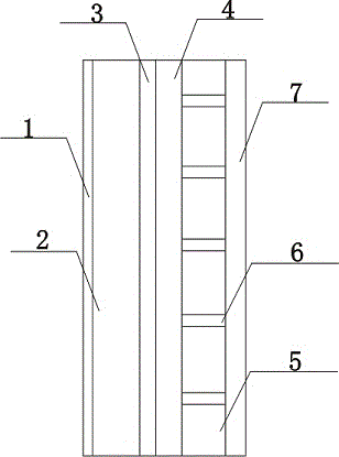
[0015] Such as figure 1 The preferred embodiment of the steel formwork structure of the present invention shown includes an outer guard plate 1, the inner side of the outer guard plate 1 is provided with a rib plate 2, and a detachable screw is connected between the rib plate 2 and the outer guard plate 1, and the rib plate 2 The inner surface is connected with a reinforcing rib 3, and the reinforcing rib 3 is connected with the rib plate 2 through reinforcing screws. A deflector 5 is provided on the inner side of the edge 4, and a sealing gasket is connected between the deflector 5 and the outer edge 4 of the vertical rib, and the outer edge 4 of the vertical rib is c...


PUM


Abstract

The present invention discloses a steel formwork structure. The steel formwork structure comprises an outer protection plate; an inner side surface of the outer protection plate is provided with a ribbed plate; detachable screws are connected between the ribbed plate and the outer protection plate; an inner side surface of the ribbed plate is connected with a reinforcing rib; the reinforcing rib is connected with the ribbed plate via reinforcing screws; an inner side surface of the reinforcing rib is connected with a vertical rib outer rim; the vertical rib outer rim is bonded with the reinforcing rib; an inner side surface of the vertical rib outer rim is provided with a flow deflector; a sealing gasket is connected between the flow deflector and the vertical rib outer rim; the vertical rib outer rim is clamped to the flow deflector; the flow deflector is provided with more than three deflector holes; a side surface of the flow deflector is connected with a securing plate; the securing plate is of a hard steel structure; and the securing plate is fixedly connected with the flow deflector. The steel formwork structure is higher in integrated structural property and bearing capacity, and is resistant to corrosion, has tight seams between formworks and smooth moulding surfaces, and has a certain deflector effect, construction quality is effectively guaranteed, and construction efficiency is improved.

Description

technical field [0001] The invention relates to a formwork structure, in particular to a steel formwork structure. Background technique [0002] In the construction industry, formwork is one of the important tools in concrete structures, especially when pouring some support panels, it is usually necessary to assemble or customize rectangular formwork. At present, the formwork used in large quantities in construction includes steel formwork and wooden formwork. There are two types of formwork. Although the steel formwork has high strength and durability, it is heavy and expensive. At the same time, due to the good affinity between concrete and steel formwork, it is not easy to disassemble the concrete after solidification, which increases the installation, disassembly and transportation during the construction process. Due to the unevenness of the steel formwork itself and the insufficient surface finish, the resulting construction surface is also uneven, and it also needs to...

Claims


Application Information

Patent Timeline
Patent Type & Authority Applications(China)
IPC IPC(8): E04G9/06
Inventor 文国栋
Owner HEBEI ROAD & BRIDGE GROUP
Learn More