
Vehicular air filtering device

A technology of air filtration and air diversion, which is applied in the directions of fuel air filter, combustion air/combustion-air treatment, charging system, etc. Easy operation and wide installation effect

Inactive Publication Date: 2015-09-02
汤明涛
View PDF5 Cites 0 Cited by
  • Summary
  • Abstract
  • Description
  • Claims
  • Application Information

AI Technical Summary

Problems solved by technology

[0003] In order to solve the current technical problem that the vehicle air filter is prone to clogging and failure under severe conditions, the present invention provides a vehicle air filter device, which can perform primary filtration of the gas entering the air filter, Prevents entry of larger dust particles while enabling automatic cleaning of the unit

Method used


Image

  • Vehicular air filtering device
  • Vehicular air filtering device

Examples


Embodiment 1

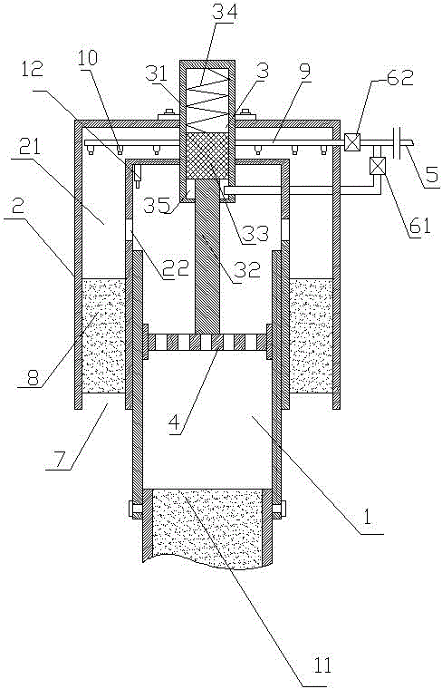
[0013] As attached figure 1 As shown, a vehicle-mounted air filter device includes an air outlet tube 1 with two ends open, and a cap 2 is provided on the top of the air outlet tube 1.

[0014] As attached figure 1 As shown, the cap 2 is a sandwich structure with a cavity 21 in the middle. The inner diameter of the cap 2 is the same as the outer diameter of the air outlet tube 1. The inner wall of the cap is provided with annularly arranged air holes 22, the air holes 22 and The inner cavity 21 of the hood penetrates, and the hood 2 can slide up and down along the air outlet tube 1. When the hood 2 slides to the bottom, the wall of the air outlet tube 1 blocks the vent 22. At this time, the lumen of the air outlet tube 1 and the hood The inner cavity 21 of the cap 2 is in an isolated state. When the cap 2 rises to the top, the vent 22 is exposed, and the lumen of the air outlet tube 1 and the inner cavity 21 of the hood penetrate through the vent 22.

[0015] In this embodiment, th...

Embodiment 2

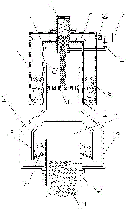
[0023] Because the working environment of vehicles is very different, when vehicles work in high dust and harsh environments, such as deserts, coal mines, construction sites, etc., even if the air is initially filtered, it is inevitable that larger particles will be sucked into the air filter. In order to solve this technical problem, this embodiment is further improved on the basis of the device provided in Embodiment 1.

[0024] As attached figure 2 As shown, in this embodiment, an oil filter device is provided below the outlet pipe 1 of the device provided in embodiment 1. The oil filter device includes an oil storage chamber 13, and the top of the oil storage chamber is connected to the end of the outlet pipe 1 And the inner cavity of the oil storage chamber 13 is connected with the outlet pipe 1, and a secondary outlet pipe 14 is provided in the oil storage room. The bottom end of the secondary outlet pipe 14 passes through the bottom plate of the oil storage room 13, and t...


PUM


Abstract

The invention relates to an air filtering device and aims to solve the technical problems of proneness to blockage and failure of an existing vehicular air filtering device under severe conditions. The vehicular air filtering device comprises an air outlet pipe, a cap of an interlayer structure is arranged at the top of the air outlet pipe, the internal diameter of the cap is consistent with the external diameter of the air outlet pipe, and the inner wall of the cap is provided with an annular vent hole communicated with an inner cavity of the cap. A lifting device is arranged on the cap and can drive the cap to move up and down at the top of the air outlet pipe, a primary-filtering filtering element is arranged in an air inlet passage at the bottom of the interlayer of the cap, an annular air feeding pipe is arranged in a top hollow cavity of the interlayer of the cap and is connected with a high-pressure air pipe through a flushing electromagnetic valve, and a plurality of air nozzles are arranged on the air feeding pipe and point to the primary-filtering filtering element. The vehicular air filtering device is reasonable in structure and simple and convenient to operate and can be widely mounted on vehicles frequently working in severe environments.

Description

Technical field [0001] The invention relates to an air filter device, in particular to an air filter device used for vehicles. Background technique [0002] Automobile air filter is mainly responsible for removing particulate impurities in the air. When the piston type machinery is operating, if the inhaled air contains dust and other impurities, it will increase the wear of the parts, so an air filter must be installed. The air filter is composed of a filter element and a housing. The main requirements of the air filter are high filtration efficiency, low flow resistance, and continuous use for a long time without maintenance. At present, the active areas of some heavy-duty trucks are mainly concentrated in high dust and harsh environments such as construction sites and mining areas. The service life of the air filter is significantly shortened. When the air filter cannot be cleaned or replaced in time, the vehicle will cause serious damage. Damage. Summary of the inventio...

Claims


Application Information

Patent Timeline
Patent Type & Authority Applications(China)
IPC IPC(8): F02M35/024F02M35/08
Inventor 汤明涛
Owner 汤明涛
Learn More