Multi-mode-control configurable-type complementary on-chip negative voltage charge pump circuit

A charge pump and configuration-type technology, which is applied in the direction of electrical components, output power conversion devices, and conversion equipment without intermediate conversion to AC, can solve the problem that the output voltage cannot maintain a continuous and stable state, and cannot generate configurable output negative pressure , unable to meet high-precision requirements and other problems, to achieve the effect of flexible and convenient use, accurate transmission level, and improved flexibility

Active Publication Date: 2015-09-02
NO 771 INST OF NO 9 RES INST CHINA AEROSPACE SCI & TECH
View PDF6 Cites 15 Cited by
  • Summary
  • Abstract
  • Description
  • Claims
  • Application Information

AI Technical Summary

Problems solved by technology

[0006] First, the working mode is single. If the charge pump is damaged or it is in a high-impedance state before it is enabled, the use of this circuit in the system will pose a great threat to the working state of the system, and even cause the system to fail to work normally.
[0007] Second, the charge pump only charges or discharges part of a clock cycle, and its output voltage cannot maintain a continuous and stable state, which will inevitably lead to a large output ripple value.
This feedback loop can only stabilize the output voltage to a certain extent, but it cannot meet the high precision requirements
[0008] Third, the system can only generate a multiplied negative voltage of the power supply voltage, but cannot generate a configurable output negative voltage, and the flexibility is low

Method used


Image

  • Multi-mode-control configurable-type complementary on-chip negative voltage charge pump circuit
  • Multi-mode-control configurable-type complementary on-chip negative voltage charge pump circuit
  • Multi-mode-control configurable-type complementary on-chip negative voltage charge pump circuit

Examples


Embodiment Construction

[0032] The present invention will be described in further detail below in conjunction with the accompanying drawings.

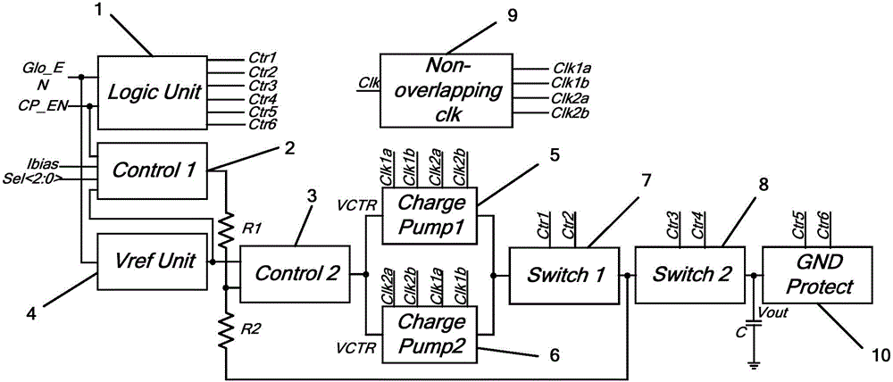
[0033] see figure 2 , the present invention includes a logic unit 1, a control unit, a reference voltage generating unit 4, a feedback resistor, a charge pump unit, a switch unit, a non-overlapping clock generating unit 9, and a grounding protection unit 10;

[0034] The logic unit 1 is connected to the system enable signal terminal Glo_EN and the charge pump enable signal terminal CP_EN; the control unit includes a first control unit 2 and a second control unit 3, the first control unit 2 is connected to the charge pump enable signal terminal CP_EN, and the bias The current input terminal, the input voltage selection signal terminal and the signal output terminal of the reference voltage generation unit 4, the second control unit 3 is connected to the reference voltage generation unit 4 and the signal output terminal of the first control unit 2; the output ...


PUM


Abstract

A multi-mode-control configurable-type complementary on-chip negative voltage charge pump circuit comprises a logical unit, a control unit, a reference voltage generating unit, a feedback resistor, a charge pump unit, a switch unit, a non-overlapping clock generation unit and a grounding protection unit. The logical unit is connected to a system enabling signal end and a charge pump enabling signal end. The control unit comprises a first control unit and a second control unit. The first control unit is connected to the charge pump enabling signal end, a bias current input end, an input voltage selection signal end and a reference voltage generation unit signal output end. The charge pump unit comprises a first charge pump and a second charge pump which are arranged in parallel. The first charge pump and the second charge pump are connected to an output signal of the non-overlapping clock generation unit in a complementary state. The switch unit comprises a first switch unit and a second switch unit which are arranged in series. An output end of the second switch unit is connected to the grounding protection unit and a ground wire respectively. By using the circuit of the invention, a voltage ripple can be restrained and an output voltage can be configured flexibly.

Description

technical field [0001] The invention belongs to the field of power management, and in particular relates to a multi-mode control configurable negative-voltage charge pump circuit on a complementary chip. Background technique [0002] A charge pump is a circuit that uses a combination of switches and pump capacitors to transfer charge from the input to the output and provide the current required by the load. The advantages of high efficiency, low noise, and low cost make the charge pump circuit one of the hottest members in the power management family. [0003] Chinese utility model patent CN203643879U titled "negative voltage adjustment circuit" discloses a schematic diagram of an existing charge pump system module, such as figure 1 shown. The system block consists of a voltage comparator, charge pump, feedback resistor and load resistor. The reference voltage Vref is connected to one end of the feedback resistor R1, and the other end is respectively connected to the same...

Claims


Application Information

Patent Timeline
Patent Type & Authority Applications(China)
IPC IPC(8): H02M3/07H02M1/14
Inventor 肖筱
Owner NO 771 INST OF NO 9 RES INST CHINA AEROSPACE SCI & TECH
Why Eureka
Try Eureka