Turbine device, and waste heat recovery power generation system including same

A turbine and power generation unit technology, which is applied in the field of turbine devices and waste heat recovery power generation systems, can solve the problems associated with turbines and oil leakage, and achieve the effects of prolonging life and eliminating friction

Active Publication Date: 2015-09-02
浦项股份有限公司
View PDF10 Cites 8 Cited by
  • Summary
  • Abstract
  • Description
  • Claims
  • Application Information

AI Technical Summary

Problems solved by technology

[0013] In particular, this type of mechanical contact bearing uses conventional oil (lubricating oil), so there is also a problem of oil leakage
In addition, the existing system uses steam or high-temperature gas, so there is a problem of water hammer accompanying the turbine

Method used


Image

  • Turbine device, and waste heat recovery power generation system including same
  • Turbine device, and waste heat recovery power generation system including same
  • Turbine device, and waste heat recovery power generation system including same

Examples


Embodiment Construction

[0036] Hereinafter, preferred embodiments of the present invention will be described (with reference to the drawings). However, the embodiments of the present invention can be modified in various other ways, and the scope of the present invention is not limited to the embodiments described below. In addition, the embodiments of the present invention are provided to more completely describe the present invention to those skilled in the art (the shapes and sizes of elements in the drawings may be exaggerated for a clearer description).

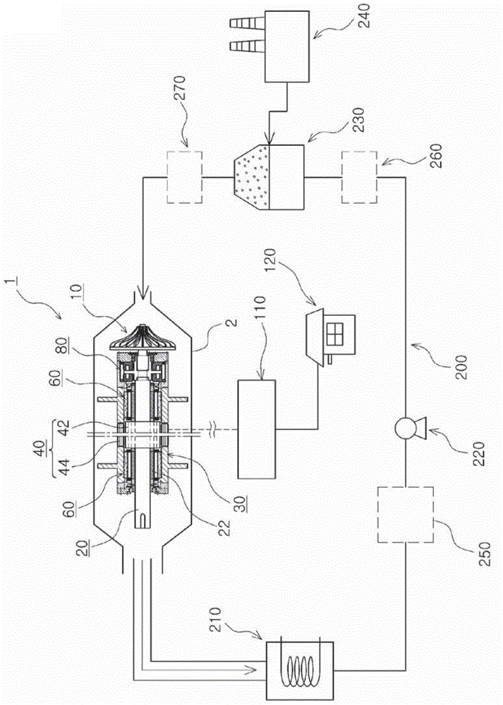
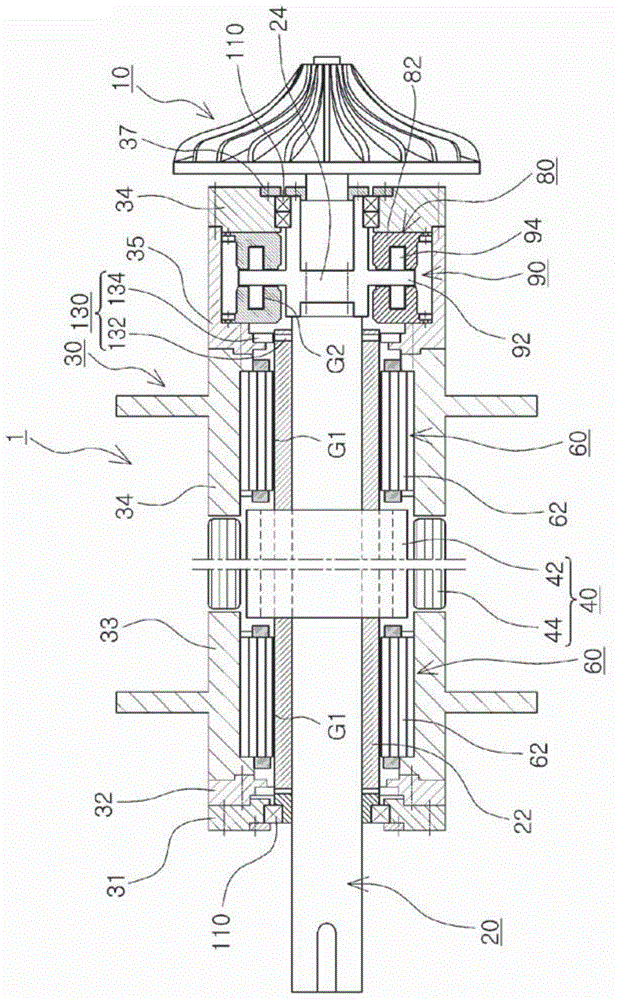
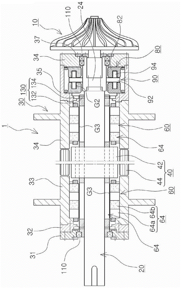
[0037] figure 1 2 to 6 show the detailed structure of the waste heat recovery power generation system (200) including the turbine device of the present invention and the turbine device (1).

[0038] First, the turbine device ( 1 ) of the present invention will be described based on FIGS. 2 to 6 , and then a waste heat recovery power generation system ( 200 ) including the turbine device of the present invention will be described.

[0039] in a...


PUM


Abstract

Provided are a turbine device and a waste heat recovery power generation system including same. According to the present invention, a mechanical (contact) type bearing structure is replaced with a contactless electromagnetic bearing so as to extend the lifespan of a turbine and increase power generation efficiency. The use of waste heat can be facilitated, and the operation of the device can be maintained stably through the improvement of a structure of a disk means and an appropriate arrangement of a mechanical bearing means.

Description

technical field [0001] The present invention relates to a turbine device, and in more detail, relates to a non-contact electromagnetic bearing instead of a mechanical (contact) bearing structure to prolong the life of the turbine, improve power generation efficiency, and easily utilize waste heat. On the other hand, by The improvement of the structure of the wheel disk unit and the proper configuration of the mechanical bearing unit to stably keep the turbine device in operation, and the present invention relates to a waste heat recovery power generation system including the same. Background technique [0002] Generally, power stations are classified into hydroelectric power stations, thermal power stations, nuclear power stations, or composite power stations, etc., according to the type of energy used and the method of power generation. [0003] On the other hand, in recent years, research has focused on recovering waste heat generated in industrial systems and applying it ...

Claims


Application Information

Patent Timeline
Patent Type & Authority Applications(China)
IPC IPC(8): F01K25/10F01D15/10F01D25/16F16C32/04
CPCF05D2220/64F01D25/16F16C2360/23F01D15/10F01K7/16F01K13/00F05D2220/62F05D2240/515F16C32/04F16C2360/00F22B1/18F01K25/10
Inventor 张泰仁权容焄池昌运金正国
Owner 浦项股份有限公司
Why Eureka
Try Eureka