heat exchanger

A heat exchanger and heat medium technology, applied in the direction of heat exchange equipment, indirect heat exchangers, heat exchanger types, etc., can solve the problems of heat exchange volume reduction, heat exchanger performance degradation, etc., to suppress the increase of pressure loss, Effects of suppressing performance degradation and suppressing refrigerant drift

Active Publication Date: 2018-04-06
DAIKIN IND LTD
View PDF9 Cites 0 Cited by
  • Summary
  • Abstract
  • Description
  • Claims
  • Application Information

AI Technical Summary

Problems solved by technology

In this way, there is a problem that the performance of the entire heat exchanger is lowered due to a decrease in the heat exchange amount at the lower flat porous tube among the plurality of flat porous tubes.

Method used


Image

  • heat exchanger
  • heat exchanger
  • heat exchanger

Examples


Embodiment Construction

[0055] Hereinafter, embodiments of the present invention will be described with reference to the drawings. In addition, embodiment of the heat exchanger of this invention is not limited to embodiment demonstrated below, It can change in the range which does not deviate from the summary of invention.

[0056] The heat exchanger 10 of the present invention is used for heat exchange between HFC refrigerants including R407C, R410A, R134a and R32, HFO refrigerants including 2,3,3,3-tetrafluoro-1-propane (HFO-1234yf), etc. A heat exchanger that performs heat exchange between a refrigerant that undergoes a phase change and other heat media. As the refrigerant used, carbon dioxide (CO2) is not included 2 )Refrigerant. In addition, in the following, the case where water is used as another heat medium that exchanges heat with the refrigerant is described as an example, but the other heat medium is not limited to water.

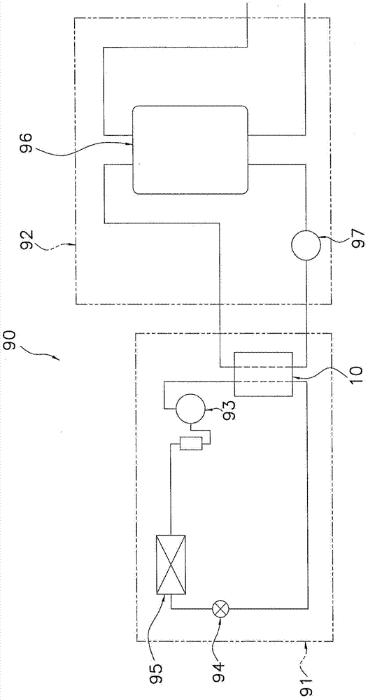
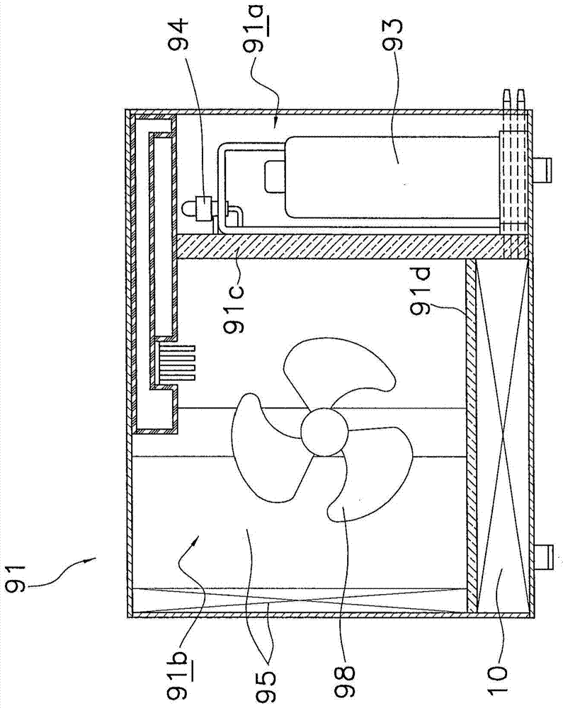
[0057] (1) Structure of heat pump hot water supply device

[00...


PUM


Abstract

The heat exchanger (10) performs heat exchange between the refrigerant that undergoes phase change during heat exchange and other heat media, wherein the heat exchanger is equipped with a refrigerant header (50), a plurality of flat porous tubes (40) and A plurality of flat tubes (20). Refrigerant flows inside the refrigerant header (50). The flat porous tube (40) extends in a direction intersecting the longitudinal direction of the refrigerant header (50). In addition, a plurality of refrigerant passages through which the refrigerant flows are formed in the flat porous tube (40). The flat tubes (20) and a plurality of flat porous tubes (40) are alternately stacked. In addition, the inside of the flat tube (20) is used for other heat medium to flow. And, the refrigerant header (50) is arranged to extend in the horizontal direction.

Description

technical field [0001] The present invention relates to heat exchangers. Background technique [0002] Conventionally, there is a heat exchanger in which a plurality of flat porous tubes in which a plurality of refrigerant flow paths are formed and a plurality of flat tubes in which other heat medium flows are alternately stacked. In such a heat exchanger, for example, as disclosed in Patent Document 1 (Japanese Unexamined Patent Application Publication No. 2007-17133), the ends of the respective flat porous tubes are connected to headers along the edges of the flat porous tubes. The longitudinal directions extend in directions intersecting each other, and the refrigerant passages of the flat porous tubes communicate with each other through the inner spaces of the headers. Contents of the invention [0003] The problem to be solved by the invention [0004] However, when a refrigerant that undergoes a phase change during heat exchange is used as the refrigerant flowing i...

Claims


Application Information

Patent Timeline
Patent Type & Authority Patents(China)
IPC IPC(8): F28F9/26F28D7/00F28F1/02
CPCF28F1/40F28D1/0333F28D1/0461F28D1/05391F28D7/0025F28D7/0083F28F1/022F28D2021/0061F25B39/04F25B2339/047F28D9/0043F28F2009/0297F28D7/0066F28D21/00F28D2021/0064
Inventor 吉冈俊松尾伸彦太田尚吾赤井宽二楮原绚人吉田香里
Owner DAIKIN IND LTD
Why Eureka
Try Eureka