A kind of method and device of multi-layer slag smelting reduction ironmaking

A smelting furnace and flux technology, applied in furnaces, furnace types, fluidized bed furnaces, etc., can solve the problems of not realizing industrialization, increasing coal consumption, large investment, etc., to simplify the smelting reduction process, improve utilization efficiency, and high energy efficiency. Effect

Active Publication Date: 2017-07-21
CENT IRON & STEEL RES INST +1
View PDF3 Cites 0 Cited by
  • Summary
  • Abstract
  • Description
  • Claims
  • Application Information

AI Technical Summary

Problems solved by technology

[0002] The ironmaking technology in the metallurgical industry has long been based on the long process of blast furnace smelting, that is, the ore powder must first be sintered or pelletized into blocks, and then enter the blast furnace after it has a certain strength. At the same time, the fuel in the blast furnace smelting process is mainly Coke, which determines the shortcomings of blast furnace ironmaking process, such as long process, high energy consumption, heavy pollution, and large investment
[0003] Aiming at the problems of traditional blast furnaces, the majority of metallurgists have been looking for a non-blast furnace ironmaking process with a short process, less coke or no coke. There have been industrialized processes such as COREX and FINEX. However, COREX is The original blast furnace process is divided into two stages of reduction and melting. Although the coke consumption is reduced, the coal consumption is increased, and the overall energy consumption is higher than that of the blast furnace. The FINEX process is also carried out in two stages of multi-stage reduction and melting. Among them, the reduction The final ore powder still needs to be compacted to enter the melter gasifier, and a small amount of coke or coking coal is also required in the smelting process
The one-step smelting reduction method that is only in the experimental stage also includes DIOS in Japan, AISI in the United States, HIsmelt in Australia and Romelt in Russia, etc. Although these processes all carry out reduction and melting of fine ore in a furnace, there are some The slag powder falls from the top, and some are sprayed into the slag. At the same time, all the combustion-supporting gases are blown from the top. However, during the test of these processes, there are serious refractory burning losses, high energy consumption, and unsmooth processes. line and other issues, therefore, has not yet achieved industrialization
[0004] In short, in the current non-blast furnace process, there are still many unresolved problems in the one-step smelting method, such as the low utilization efficiency of CO gas generated during the smelting process, which is burned at the top of the furnace, or incompletely burned

Method used


Image

  • A kind of method and device of multi-layer slag smelting reduction ironmaking
  • A kind of method and device of multi-layer slag smelting reduction ironmaking
  • A kind of method and device of multi-layer slag smelting reduction ironmaking

Examples


Embodiment 1

[0055] Mineral powder: Iron ore powder, containing 54% iron, with a particle size of less than 100 mesh.

[0056] Flux: quicklime powder, CaO content 81%, particle size less than 100 mesh; dolomite powder, CaO content 29%, MgO content 19%, particle size less than 100 mesh.

[0057] Fuel: coal powder, fixed carbon content 79%, particle size less than 100 mesh.

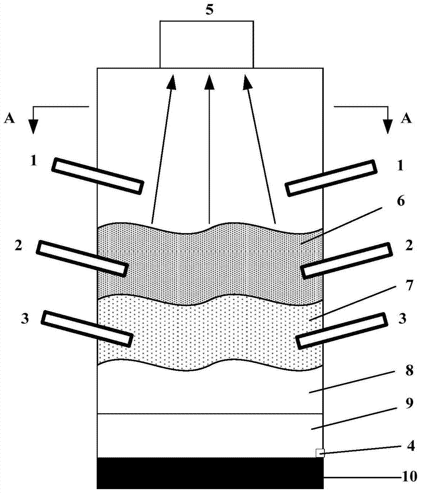
[0058] After mixing iron ore powder and flux (quicklime powder and dolomite powder) in a certain proportion, spray the mixture and oxygen-enriched air (oxygen-enriched rate 10%) at a temperature of 900°C into the molten slag layer 6 from the middle spray gun 2 In the process, the pressure of the oxygen-enriched air is 0.1Mpa, the oxygen-enriched air sprayed into the molten slag layer reacts with the CO gas entering the molten slag layer from the reducing slag layer to release heat, and melts the iron ore powder and part of the flux to form a certain smelting slag .

[0059] Spray pulverized coal and oxygen-enriched ai...

Embodiment 2

[0064] Mineral powder: copper tailings powder, containing 40% iron, particle size less than 100 mesh.

[0065] Flux: quicklime powder, CaO content 82%, particle size less than 100 mesh.

[0066] Fuel: coal powder, fixed carbon content 81%, particle size less than 100 mesh.

[0067] After mixing copper tailings powder and flux (quicklime powder) in a certain proportion, spray the mixture and pure oxygen at 25°C into the molten slag layer 6 from the middle layer spray gun 2, the pressure of pure oxygen is 0.15Mpa, spray into The pure oxygen in the molten slag layer reacts with the CO gas entering the molten slag layer from the reducing slag layer to release heat, melting the iron ore powder and part of the quicklime powder to form a certain smelting slag.

[0068] Coal powder and pure oxygen at 25°C are sprayed from the lower spray gun 3 into the reduced slag layer 7, the pure oxygen injected into the reduced slag layer reacts with the injected coal powder to produce CO, and at...


PUM

PropertyMeasurementUnit
particle sizeaaaaaaaaaa

Abstract

The invention belongs to the field of ironmaking, and relates to a method and device for ironmaking by smelting reduction of multi-layer slag. The method is carried out in a vertical smelting furnace, and a mixture of combustion-supporting gas, mineral powder + flux, combustion-supporting gas, fuel and The combustion-supporting gas is respectively fluidly connected to the upper spray gun (1), the middle spray gun (2) and the lower spray gun (3) arranged on the upper, middle and lower parts of the vertical melting furnace; the three spray guns spray the prepared materials into the vertical melting furnace at the same time. In the smelting furnace, molten iron and slag are formed by reaction, and the molten slag layer (6), the reduced slag layer (7), the static slag layer (8), the molten iron layer (9) and the dead slag layer are formed from top to bottom in the furnace. Iron layer (10); iron or slag is tapped through the iron / slag outlet (4) arranged at the molten iron layer (9) at the lower part of the furnace body. The invention is a high-efficiency, energy-saving and low-cost one-step smelting reduction ironmaking method, and the device design is simple and easy to realize.

Description

technical field [0001] The invention belongs to the field of ironmaking, in particular to a method and device for smelting reduction ironmaking. Background technique [0002] The ironmaking technology in the metallurgical industry has long been based on the long process of blast furnace smelting, that is, the ore powder must first be sintered or pelletized into blocks, and then enter the blast furnace after it has a certain strength. At the same time, the fuel in the blast furnace smelting process is mainly Coke, which determines the shortcomings of the blast furnace ironmaking process, such as long process, high energy consumption, heavy pollution, and large investment. [0003] Aiming at the problems of traditional blast furnaces, the majority of metallurgists have been looking for a non-blast furnace ironmaking process with a short process, less coke or no coke. There have been industrialized processes such as COREX and FINEX. However, COREX is The original blast furnace...

Claims


Application Information

Patent Timeline
Patent Type & Authority Patents(China)
IPC IPC(8): C21B13/00
Inventor 王锋齐渊洪严定鎏高建军许海川
Owner CENT IRON & STEEL RES INST
Why Eureka
Try Eureka