Novel walking type chassis crawler shoe structure

A walking and booting technology, which is applied in the direction of infrastructure engineering, drilling equipment, drilling equipment and methods, etc., can solve problems such as the impact of service life, skewing of the axis of the walking cylinder, troublesome assembly, etc., and achieve the improvement of load carrying capacity, The structure of the shoe is stable and the assembly is easy to improve the effect

Inactive Publication Date: 2015-09-09
湖南泰达天易重工有限公司
View PDF6 Cites 0 Cited by
  • Summary
  • Abstract
  • Description
  • Claims
  • Application Information

AI Technical Summary

Problems solved by technology

[0004] 2. The connection between the traveling wheel frame and the traveling wheel beam adopts a cantilever structure, which not only uses more materials, but also is more troublesome to assemble; the traveling wheel shaft and the cantilever shaft do not intersect on the same plane, and the traveling wheel frame has a large swing and poor stability ;
[0005] 3. The shoes and the hanger surface are severely worn during the return process, and the maintenance frequency is high;
[0006] 4. When the shoes land at the end of the return journey, they often appear not parallel, which causes wear on the flange of the running wheel and the rail, the hanger and the shoes;
[0007] 5. One end of the walking cylinder is connected to the traveling wheel beam, and the other end is set on the shoe. When the shoe swings, the traveling wheel beam does not swing, causing the axis of the walking cylinder to be skewed, which interferes with the movement of the walking cylinder and affects its service life.
[0008] 6. No matter how the use environment changes, the contact area between the boots and the ground remains unchanged. When the ground in the construction environment is soft, the contact area between the boots and the ground may be too small, and there may be conditions such as subsidence that affect the construction progress

Method used


Image

  • Novel walking type chassis crawler shoe structure
  • Novel walking type chassis crawler shoe structure
  • Novel walking type chassis crawler shoe structure

Examples


Embodiment Construction

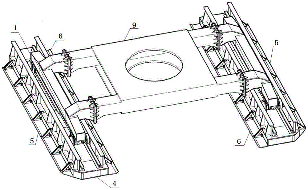
[0030] Such as figure 1 As shown, the new walking chassis shoe structure is mainly composed of two sets of parallel traveling mechanisms and a walking frame 9, the mechanical equipment is fixed on the walking frame, and the two ends of the walking frame are respectively connected with the two groups of walking mechanisms through pivot pins.

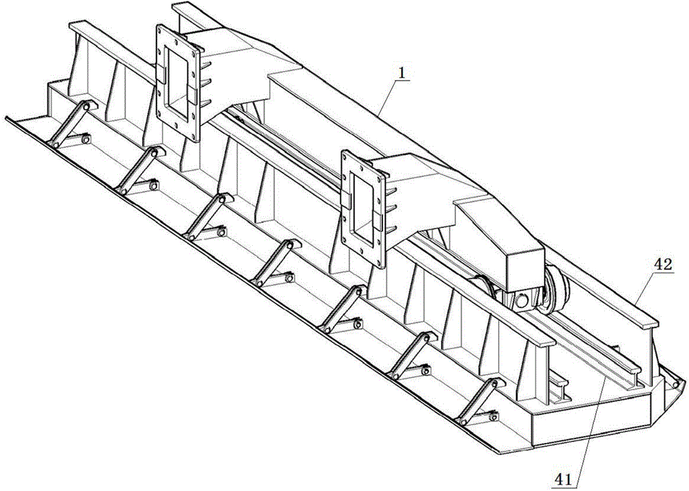
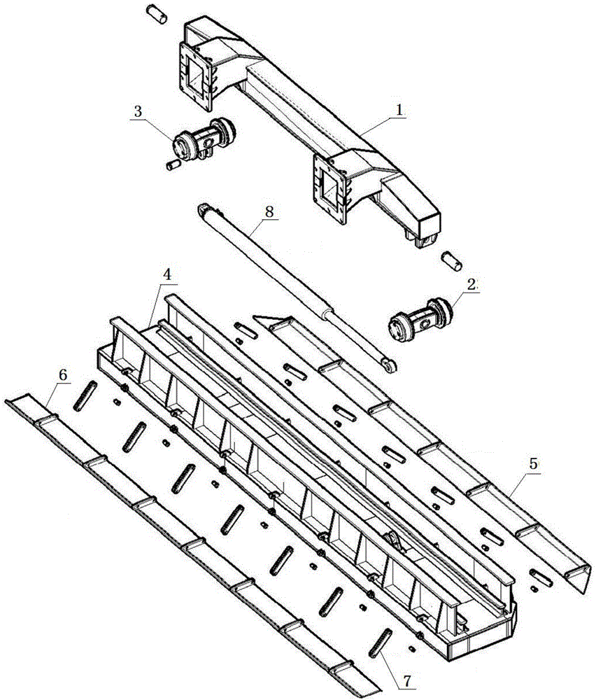
[0031] Such as Figure 2 to Figure 5 As shown, the traveling mechanism mainly includes a traveling wheel beam 1, a front traveling wheel group 2, a rear traveling wheel group 3, shoe shoes 4 and a traveling oil cylinder 8, and the traveling mechanism also includes an outer hanger 5, an inner hanger 6 and a pull rod 7 .

[0032] The outer hanger 5 and the inner hanger 6 are respectively arranged on the inner side and the outer side of the shoe 4 through the foldable tie rod 7; The wall is welded on the top wall of the external hanger or inner hanger in a vertical manner; the end of the tie rod away from the shoe shoe and one end of the t...


PUM


Abstract

A novel walking type chassis crawler shoe structure mainly comprises two sets of parallel walking mechanisms and a walking support. A mechanical apparatus is fixed on the walking support. The two ends of the walking support are connected to the two sets of parallel walking mechanisms through shaft pins. An external hanging bracket and an internal hanging bracket which can be retreated and released are arranged on the two sides of each crawler shoe body and can be used for increasing the contact area between each crawler shoe body and the ground according to construction environments. Therefore, the novel walking type chassis crawler shoe structure can work smoothly on softer construction sites and there is no need to worry about the danger of sinking; front moving wheel sets and rear moving wheel sets use universal joint pin structures and are not directly connected with moving wheel beams, so that the structure is simper, the assembly is easy and the load bearing capability is effectively improved; the return is of rolling type, so that the abrasion between parts is reduced, the parallelism between the parts can be effectively controlled and the crawler shoe structure is more stable.

Description

technical field [0001] The invention relates to a walking-type chassis shoe structure used for large-scale mechanical equipment such as piling machinery, in particular to a drilling machine walking-type chassis shoe structure, which belongs to the optimization technology of the shoe structure. Background technique [0002] There are following deficiencies in the existing drilling machine walking type chassis shoe structure: [0003] 1. The height of the shoes is small, resulting in a small bending section coefficient. It is often necessary to weld the back plate to improve the bending strength of the component, and more materials are used. [0004] 2. The connection between the traveling wheel frame and the traveling wheel beam adopts a cantilever structure, which not only uses more materials, but also is more troublesome to assemble; the traveling wheel shaft and the cantilever shaft do not intersect on the same plane, and the traveling wheel frame has a large swing and poo...

Claims


Application Information

Patent Timeline
Patent Type & Authority Applications(China)
IPC IPC(8): E21B7/02E02D7/14
Inventor 张相福李建秋肖晟
Owner 湖南泰达天易重工有限公司
Why Eureka
Try Eureka