Multi-stage submersible pump system

A submersible pump and pump pool technology, applied in the field of centrifugal pumps, can solve the problems of difficult maintenance of pump shaft seals, low reliability, and large system cold loss, and achieve the effects of small loss, improved efficiency, and low flow rate.

Active Publication Date: 2015-09-09
ZIBO BOSHAN LVYUAN GAS EQUIP CO LTD
View PDF8 Cites 6 Cited by
  • Summary
  • Abstract
  • Description
  • Claims
  • Application Information

AI Technical Summary

Problems solved by technology

Most of the existing pumps are in the form of land pumps (pumps are placed in the atmosphere), the system has a large

Method used


Image

  • Multi-stage submersible pump system
  • Multi-stage submersible pump system
  • Multi-stage submersible pump system

Examples


Embodiment Construction

[0027] Embodiments of the present invention are further described below in conjunction with accompanying drawings:

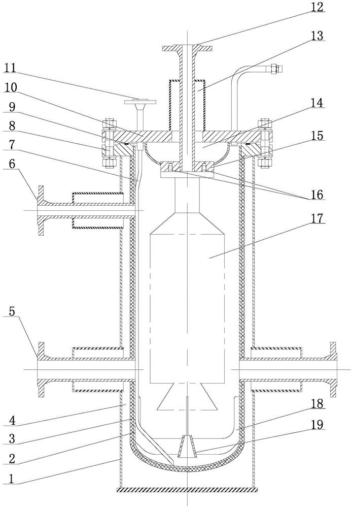
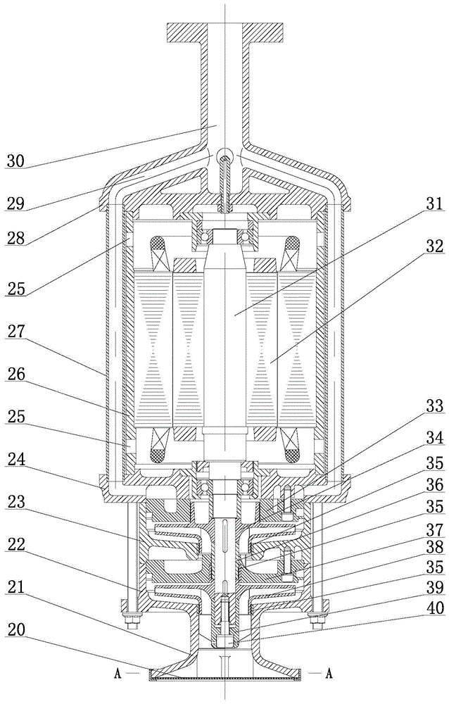
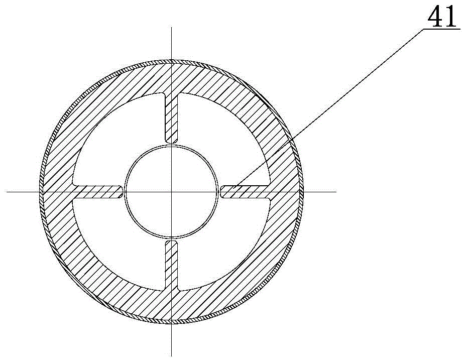
[0028] like Figure 1~3As shown, the multistage submersible pump system of the present invention includes a pump pool and a pump body 17, the pump body 17 is installed in the pump pool, and the pump body 17 includes a pump casing, a motor rotor 32, a central shaft 31 and a shaft end screw 40 The inducer 39, the first-stage impeller 38, the first-stage guide vane 37, the shaft sleeve 36, the last-stage impeller 34 and the last-stage guide vane 33 fastened on the central shaft 31, the pump casing includes sequentially connected from bottom to top The suction section 22, the middle section 23, the lower end cover 24, the motor housing 26 and the upper end cover 28, the upper end cover 28 adopts integral casting, the upper and lower end covers are connected through at least 4 outlet pipes 27, each flow channel in the upper end cover 28 29 and the cross-section of t...


PUM


Abstract

The invention belongs to the field of centrifugal pumps and particularly relates to a multi-stage submersible pump system. The system comprises a pump pond and a pump body. A pump casing comprises a suction section, a middle section, a lower end cover, a motor casing and an upper end cover. The upper end cover is integrally cast formed, the upper and lower end covers are communicated through at least four liquid outlet tubes, sections of flow channels in the upper end cover and the liquid outlet tubes are circular, and the flow channel and liquid outlet tube connection positions are in smooth transition. A horn tube is arranged on the lower portion of the suction section, and two to six of first guide sheets are distributed along the inner circumference of the horn tube uniformly. A suction filter screen is arranged at the suction end of the horn tube, exhaust holes are formed in the upper and lower portions of the motor casing respectively, and a triangular labyrinth groove is formed in the first-stage impeller, final-stage impeller and shaft sleeve clearance fit positions respectively. According to the system, the pump body suction efficiency is high, the pump pond thermal-insulation effect is good, the flexibility and the economy of the whole system are improved due to the final-stage guide blade unique structure, and by the aid of the axial force balance and bearing lubrication structure, the axial force can be balanced, and the pressure and the flow of bearing lubrication liquids are guaranteed.

Description

technical field [0001] The invention relates to a multistage submersible pump system, which belongs to the field of centrifugal pumps. Background technique [0002] Cryogenic liquids such as liquid nitrogen and liquefied natural gas have the characteristics of low temperature (at atmospheric pressure, liquid nitrogen is -196°C, liquefied natural gas is -161°C), dangerous, and easy to gasify. Low temperature, shaft seal should have no medium leakage, system cold loss should be as small as possible, etc. Most of the existing pumps are in the form of land pumps (pumps are placed in the atmosphere), the system has a large cold loss, and the pump shaft seal is difficult to maintain, prone to medium leakage, and the reliability is not high. Contents of the invention [0003] Based on the above deficiencies in the prior art, the technical problem to be solved by the present invention is to provide a multi-stage submersible pump system with low flow loss of cryogenic liquid, less...

Claims


Application Information

Patent Timeline
IPC IPC(8): F04D13/08F04D29/58F04D29/046F04D29/44
Inventor 翟鲁涛岳军宗秀山
Owner ZIBO BOSHAN LVYUAN GAS EQUIP CO LTD
Why Eureka
Try Eureka