Array antenna beam forming method
A beamforming method and array antenna technology, applied in antennas, diversity/multi-antenna systems, radio transmission systems, etc., can solve the problems of time-consuming optimization process and inability to approach the ideal pattern
- Summary
- Abstract
- Description
- Claims
- Application Information
AI Technical Summary
Problems solved by technology
Method used
Image
Examples
example 1
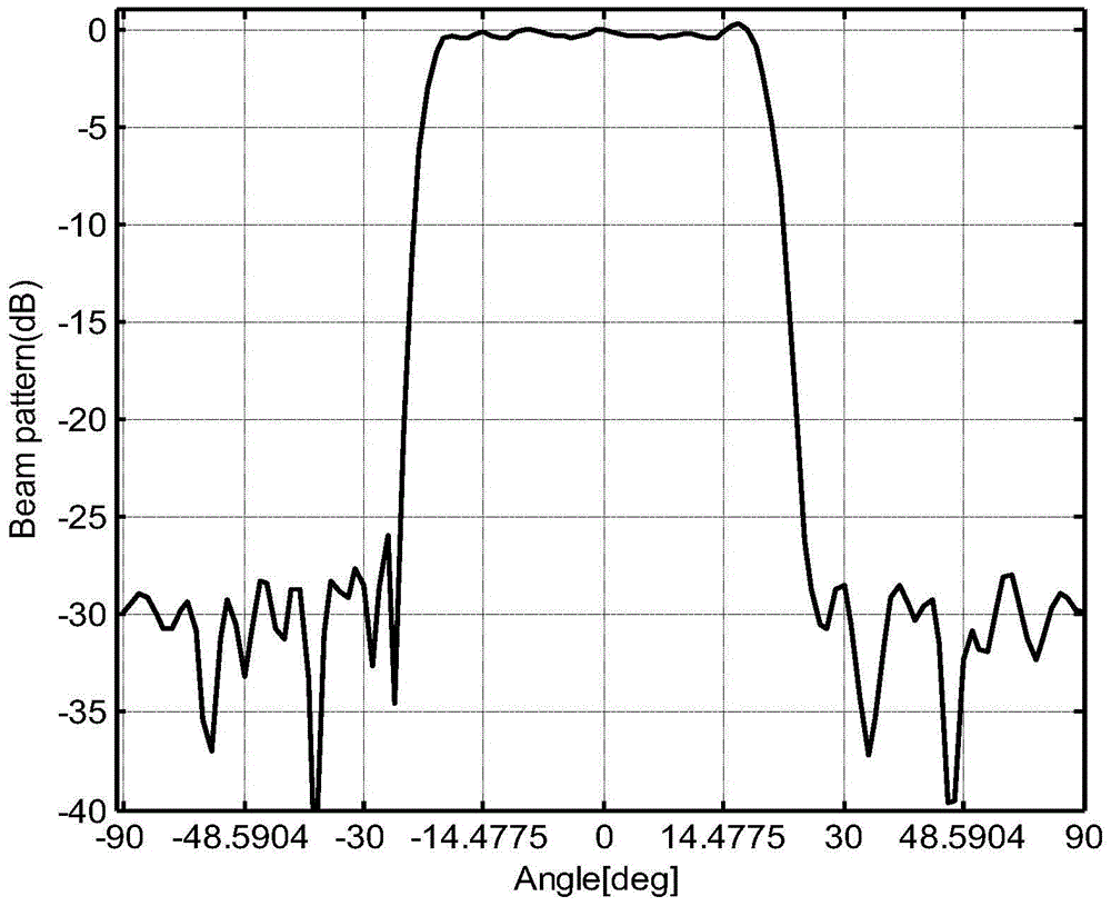
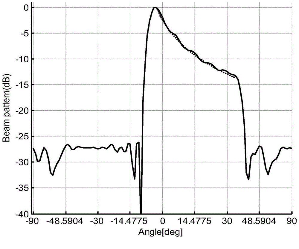
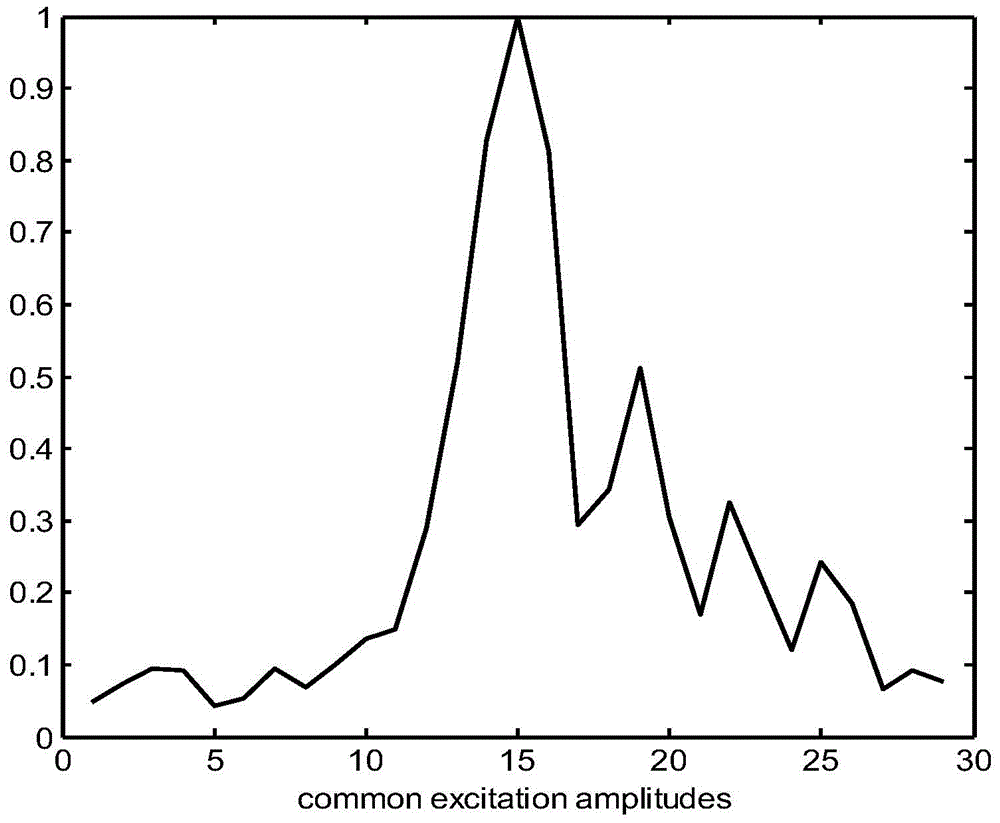
[0037] Example 1: The linear array antenna consists of 29 elements, the element spacing is 0.5λ, the constraints are that the main lobe of the flat top beam is |sinθ|≤0.41, the ripple is 0.1, the side lobe is -25dB, and the cosecant square shapes the left side lobe The range is -1≤sinθ≤-0.15, the range of the right sidelobe is 0.7≤sinθ≤1, the range of the main lobe is -0.034≤sinθ≤0.6, the ripple is 0.1, and the sidelobe is -25dB. Table 1 shows the different phase values of the same power for each pattern.
[0038] Table 1
[0039] unit
PUM
 Abstract
Description
Claims
Application Information
 - R&D
- Intellectual Property
- Life Sciences
- Materials
- Tech Scout
- Unparalleled Data Quality
- Higher Quality Content
- 60% Fewer Hallucinations
Browse by: Latest US Patents, China's latest patents, Technical Efficacy Thesaurus, Application Domain, Technology Topic, Popular Technical Reports.
© 2025 PatSnap. All rights reserved.Legal|Privacy policy|Modern Slavery Act Transparency Statement|Sitemap|About US| Contact US: help@patsnap.com


