


Quick Research
Generate reliable direction feasibility study reports for your R&D in just a few steps.

Technical Q&A
Discover and master advanced knowledge NOW. Basics, ideas, possibilities, all at once.

Find Solutions
As an expert in R&D theories, this can generate solutions to your technical problems instantly.

Evaluate Feasibility
Analyze your overall solution with one click, know your potential R&D risks in advance.

Monitor Landscape
Get weekly tech updates, stay abreast of the latest tech innovations and key insights.
Metal catalyst carrier manufacturing method, metal catalyst carrier, fuel cell manufacturing method, and catalyst-carrying device
A technology of metal catalysts and manufacturing methods, applied in the direction of solid electrolyte fuel cells, fuel cells, metal/metal oxides/metal hydroxide catalysts, etc., can solve the problem of insufficient research on metal catalysts, no disclosure of metal catalysts, etc. question
- Summary
- Abstract
- Description
- Claims
- Application Information
AI Technical Summary
Problems solved by technology
Method used
Image

Examples
no. 1 approach
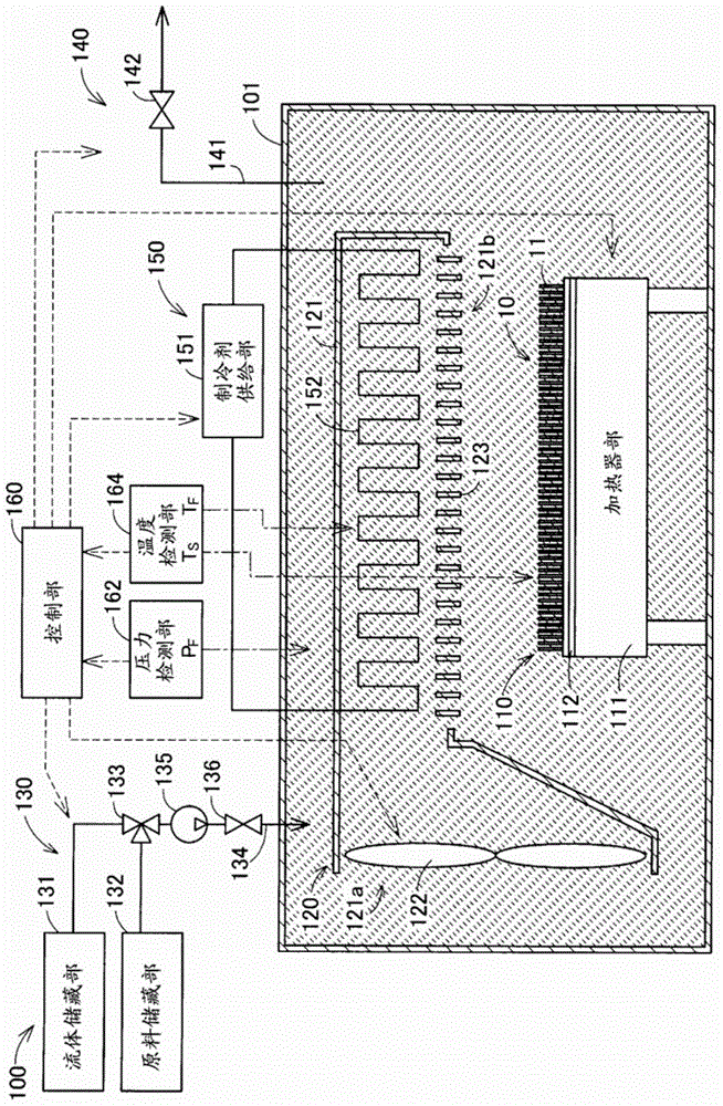
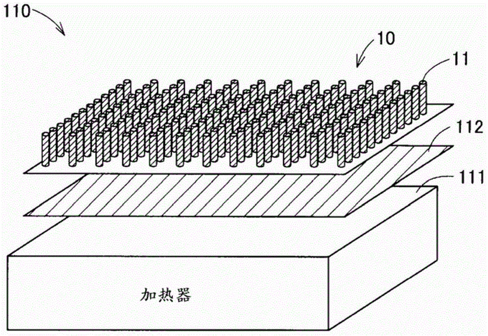
[0034] figure 1 It is a schematic diagram showing the structure of a catalyst supporting device as one embodiment of the present invention. This catalyst loading device 100 loads a metal catalyst on a carrier using a supercritical fluid. In addition, in this embodiment, carbon dioxide in a supercritical state (hereinafter also referred to as "supercritical carbon dioxide") is used as the supercritical fluid. In addition, in the present embodiment, carbon nanotubes (hereinafter referred to as "CNTs") are used as carriers, and platinum (Pt) as a metal catalyst is supported on them.
[0035] The catalyst loading device 100 includes a processing chamber 101 , a carrier arrangement unit 110 , a fluid circulation nozzle 120 , a fluid supply unit 130 , a fluid discharge unit 140 , a fluid temperature control unit 150 , a control unit 160 , a pressure detection unit 162 and a temperature detection unit 164 . The processing chamber 101 is an airtight chamber capable of being filled w...
Embodiment 1
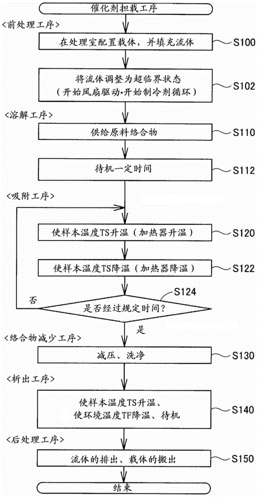
[0090] Figure 8 ) The treatment conditions of the adsorption process>
[0091] Process time: about 8 hours
[0092] Ambient temperature T F : About 45℃~50℃
[0093] Sample temperature T S Variation range: 50~120℃
[0094] Sample temperature T S The number of changes: 10 times (approximately constant cycle)
Embodiment 2
[0095] Figure 9 ) The treatment conditions of the adsorption process>
[0096] Process time: about 5 hours
[0097] Ambient temperature T F : About 45℃~50℃
[0098] Sample temperature T S Variation range: 50~120℃
[0099] Sample temperature T S The number of changes: 5 times (approximately constant cycle)
[0100] Figure 10 ) The treatment conditions of the adsorption process>
[0101] Process time: about 8 hours
[0102] Ambient temperature T F : About 48~50℃
[0103] Sample temperature T S Changes: None (maintained at around 120°C)
[0104] Figure 11 , Figure 12 It is an explanatory diagram for explaining the results of Examples 1 and 2 and a reference example. Figure 11 (A) shows a table summarizing a part of the treatment conditions of the adsorption step of each of Examples 1 and 2 and the reference example and the measurement results of platinum supported on CNTs. Figure 11 (B) is a graph showing the particle size distribution (number basis) of platin...
PUM
 Abstract
Description
Claims
Application Information
 - R&D Engineer
- R&D Manager
- IP Professional
- Industry Leading Data Capabilities
- Powerful AI technology
- Patent DNA Extraction
Browse by: Latest US Patents, China's latest patents, Technical Efficacy Thesaurus, Application Domain, Technology Topic, Popular Technical Reports.
© 2024 PatSnap. All rights reserved.Legal|Privacy policy|Modern Slavery Act Transparency Statement|Sitemap|About US| Contact US: help@patsnap.com