
Emergency CT medical vehicle

A technology for medical vehicles and carriages, applied in the field of vehicles, can solve the problems of limited working time of equipment in the carriage, limited capacity of emergency batteries, and limited interior space of the carriage, and achieve the effects of being beneficial to transportation, reducing volume and improving flexibility.

Inactive Publication Date: 2015-09-16
福建省富亚龙挂车制造有限公司
View PDF7 Cites 7 Cited by
  • Summary
  • Abstract
  • Description
  • Claims
  • Application Information

AI Technical Summary

Problems solved by technology

In the prior art, mobile medical vehicles are mostly improved on the basis of heavy-duty transport vehicles, and most of them are equipped with relevant medical equipment in the vehicle compartment. However, the interior space of traditional vehicles is limited, making the compartment Only a small amount of small equipment can be placed, which reduces the ability of medical services. If a CT scanning device is placed, the traditional compartment will appear very crowded, which will affect the work
In addition, due to the limited capacity of the traditional on-board emergency battery, the working time of the equipment in the car is limited. Once the medical car encounters a long-distance transportation journey, or encounters a traffic jam during transportation, or needs to work in the field and cannot be connected to the mains, the medical vehicle will not be able to connect to the mains. The power supply of the equipment has become the most difficult problem

Method used


Image

  • Emergency CT medical vehicle
  • Emergency CT medical vehicle
  • Emergency CT medical vehicle

Examples


Embodiment Construction

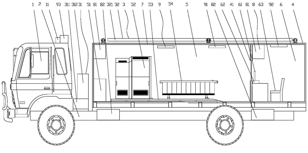
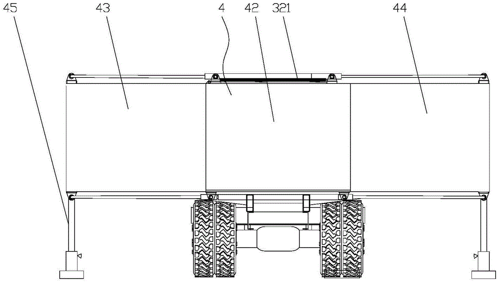
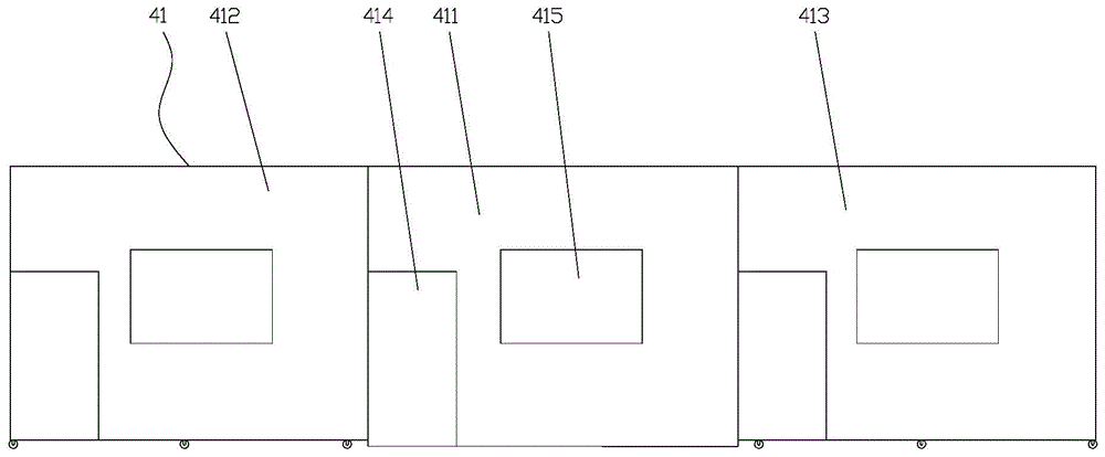
[0022] Such as Figure 1-4 As shown in one of them, the present invention includes a car cab 1 and a car chassis 2, and the car chassis 2 is provided with a power generation system 3 and a telescopic compartment 4, and the telescopic compartment 4 is provided with a telescopic partition 41, and the telescopic partition The plate 41 divides the inner space of the telescopic carriage 4 into a CT scanning room 5 and a CT control room 6 distributed front and back, and the inner walls of the CT scanning room 5 and the CT control room 6 are provided with radiation-proof panels 7, and the CT scanning room 5 is provided with an electric control box 51, a CT host 52, a shock absorbing table 53 and a scanning bed 54, the CT host 52 is arranged on the shock absorbing table 53, and the CT control room 6 is provided with a display 61, a printer 62 and a scanning table 54. The seat 63, the monitor 61 and the printer 62 are respectively connected to the CT host 52, and the power generation s...


PUM


Abstract

The invention relates to the technical field of vehicles, in particular to an emergency CT medical vehicle. The emergency CT medical vehicle comprises a vehicle cab and a vehicle chassis. A power generation system and a telescopic compartment are arranged on the vehicle chassis. A telescopic partition plate, used for separating internal space of the telescopic compartment into a CT scanning chamber and a CT control chamber, is arranged in the telescopic compartment. The CT scanning chamber and the CT control chamber are distributed back and forth. Inner walls of the CT scanning chamber and the CT control chamber are provided with radiation protection plates. An electric control box, a CT host, a shock absorption table and a scanning bed are arranged in the CT scanning chamber. The CT host is arranged on the shock absorption table. A display, a printer and a seat are arranged in the CT control chamber. The display and the printer are connected with the CT host. The power generation system, the CT host and the display are connected with the electric control box. The emergency CT medical vehicle has following beneficial effects: the emergency CT medical vehicle is reasonably designed; volume of the compartment is adjustable; a generating function is obtained; CT scanning equipment is possessed such that a patient can favorably take an examination and receives treatment as early as possible; and the emergency CT medical vehicle is especially adapted to field operation, emergency rescue, operation in the harsh environment and the like.

Description

technical field [0001] The invention relates to the technical field of vehicles, in particular to an emergency CT medical vehicle. technical background [0002] CT machine is a computer-aided imaging device that uses X-rays as the transmission energy of human body tomography. It has become a popular medical equipment for inspection and diagnosis in hospitals. Surgery provides the most valuable instructional information. my country is a country with frequent natural disasters. In recent years, natural disasters such as earthquakes, floods, and mudslides have occurred frequently. Field medical stations and mobile medical vehicles have played an important role in earthquake relief with their fast mobility. The development of the emergency CT medical vehicle provides a powerful tool for first aid. In the prior art, mobile medical vehicles are mostly improved on the basis of heavy-duty transport vehicles, and most of them are equipped with relevant medical equipment in the vehi...

Claims


Application Information

Patent Timeline
IPC IPC(8): A61B19/00A61B6/03
CPCA61B6/035A61B6/107A61B2560/0214
Inventor 官翠华陈猛凌燕
Owner 福建省富亚龙挂车制造有限公司
Learn More