Mould adjusting method used for two plate type mould clamping device

A two-plate, clamping technology, which is applied in the field of mold adjustment of two-plate injection molding machines and two-plate clamping devices, can solve the problems of low automation, rough adjustment, failure of closing and closing, etc., achieves a high degree of intelligence, and eliminates measurement Mechanical error, fast clamping force

Inactive Publication Date: 2015-09-16
佛山市顺德区凯迪威机械有限公司
View PDF4 Cites 4 Cited by
  • Summary
  • Abstract
  • Description
  • Claims
  • Application Information

AI Technical Summary

Problems solved by technology
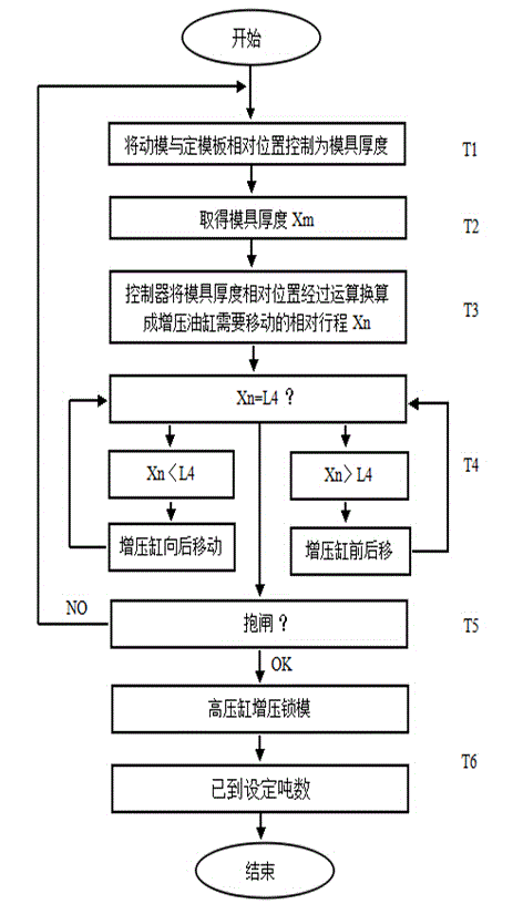
The disadvantages of the existing clamping force adjustment method of the two-platen clamping device are: time-consuming, too rough adjustment, low degree of automation, low precision, and easy to cause failure of the lock during automatic production

Method used


Image

  • Mould adjusting method used for two plate type mould clamping device
  • Mould adjusting method used for two plate type mould clamping device
  • Mould adjusting method used for two plate type mould clamping device

Examples


Embodiment Construction

[0018] Hereinafter, preferred embodiments of the present invention will be described in detail based on the drawings. In addition, the drawings of the present invention do not limit the present invention, but are used to make the present invention easier to understand. In addition, in order to avoid ambiguity of the present invention, detailed descriptions of peripheral parts are omitted.

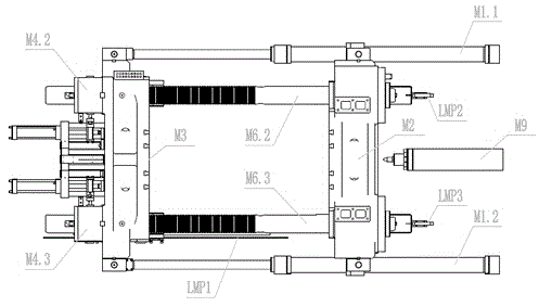
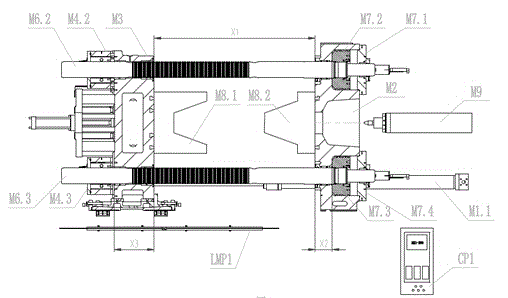
[0019] see Figure 2~Figure 5 , the present invention includes M1.1, M1.2: movable mold cylinder and connecting rod, M2: fixed template, M3: movable template, M4.1, M4.2, M4.3, M4.4: brake mechanism, M5 .1, M5.2, M5.3, M5.4: booster cylinder, M6.1, M6.2, M6.3, M6.4: Corinthian column, M7.1, M7.2, M7.3 , M7.4: booster cylinder piston, M8.1, M8.2: mold, M9: injection mechanism, LMP1: mold thickness digital position sensor, LMP2, LMP3, LMP4, LMP5: booster cylinder position sensor, S1, S2, S3, S4: Brake closing confirmation sensor, CP1: Controller, X1: Mold thickness, X2: The thickness from ...


PUM


Abstract

The present invention provides a mould adjusting method used for a two plate type mould clamping device, the method is as follows: a moving die oil cylinder and a connecting rod are driven and controlled to drive a moving die plate to draw close to a fixed die plate, the moving die plate moves until the mould is in fully closed state, 1-3 tons of clamping force is applied to the mould between the moving die plate and the fixed die plate by the moving die oil cylinder; a controller reads the current mould thickness by a digital position sensor fixed on a die plate bearing frame; the controller converts a mould thickness relative value into four pressurizing oil cylinder location ready positions generating mould clamping force; the controller drives and controls pressurizing oil cylinders to simultaneously move to the set positions; the controller drives and controls four internal contracting brake mechanisms fixed on the back side of the moving die plate to simultaneously internally contract, the controller confirms the four internal contracting brake mechanisms all are in internal contracting state by four sensors fixed on the four internal contracting brake mechanisms; the controller drives and controls the pressurizing oil cylinders to move toward injection organization direction for high pressure mould clamping and adjust to the mould clamping force to a preset tonnage.

Description

technical field [0001] The invention relates to the technical field of plastic injection molding equipment, in particular to a mold adjustment method for a two-platen injection molding machine and a two-platen clamping device. Background technique [0002] The clamping force adjustment mechanism of the existing two-plate clamping device is composed of related parts such as an oil pump, a motor, a chain transmission system, a lock mechanism, a pressurized oil cylinder, and a proximity switch. The clamping force adjustment method includes: after manually installing the mold in place, 1. Move the oil pump motor to drive the booster cylinder (Gorlin column) to the rear mechanical limit position in the direction of the moving plate; 2. Through the chain drive (including: with The gear motor of the reduction gear, the brake moving guide rod, the gap spring, the chain, etc.) will move the lock mechanism fixed on the back of the movable template to move forward and backward; When t...

Claims


Application Information

Patent Timeline
Patent Type & Authority Applications(China)
IPC IPC(8): B29C45/80
CPCB29C45/80
Inventor 梁荣球董矩潮陈邦灿饶健强
Owner 佛山市顺德区凯迪威机械有限公司
Why Eureka
Try Eureka