A kind of sludge powder mixer

A sludge powder and powder mixing knife technology, applied in mixers, sludge treatment, water/sludge/sewage treatment, etc., can solve problems such as failure to meet process requirements, difficulty in replacement, low work efficiency, etc., and achieve reduction Easy to breakage rate, improve processing efficiency, beautiful and reasonable layout effect

Active Publication Date: 2017-12-29
HUNAN JIUFANG ENVIRONMENTAL PROTECTION MACHINERY
View PDF6 Cites 0 Cited by
  • Summary
  • Abstract
  • Description
  • Claims
  • Application Information

AI Technical Summary

Problems solved by technology

[0002] With the continuous expansion of the city scale, the environmental problems caused by the sludge after urban sewage treatment have become increasingly prominent. In the composting treatment of urban sludge aerobic fermentation, it is necessary to use sludge, conditioners, and return materials in a set proportion The technical requirements of sludge aerobic fermentation can be better met only after being stirred by a machine; due to the physical and chemical characteristics of sludge and the process of stacking and storage, impurities are easily mixed in, which is not conducive to the operation of the general pulverizer, and the mixture formed by general pulverization and mixing It does not meet the technical requirements of aerobic fermentation, and anaerobic fermentation is formed in the process of aerobic fermentation, which produces stench and pollutes the environment; while the structure of ordinary sludge pulverizers requires simple materials, and dewatered sludge is a kind of sandy sludge. , flocculated substances with a lot of impurities and a moisture content of 80%, it is difficult to mix the conditioner with fine particles and low density evenly with it, and it will form agglomerates after crushing, causing the blades of the tear-shear pulverizer to wear quickly and difficult to replace, and the hammer Impact-type mixing and crushing are not uniform, the work efficiency is low, and the use effect is not good

Method used


Image

  • A kind of sludge powder mixer
  • A kind of sludge powder mixer
  • A kind of sludge powder mixer

Examples


Embodiment Construction

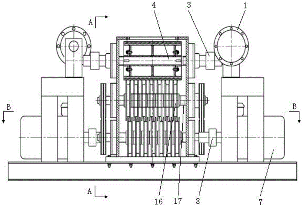
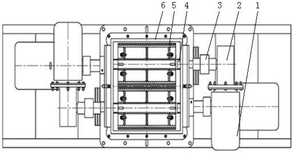
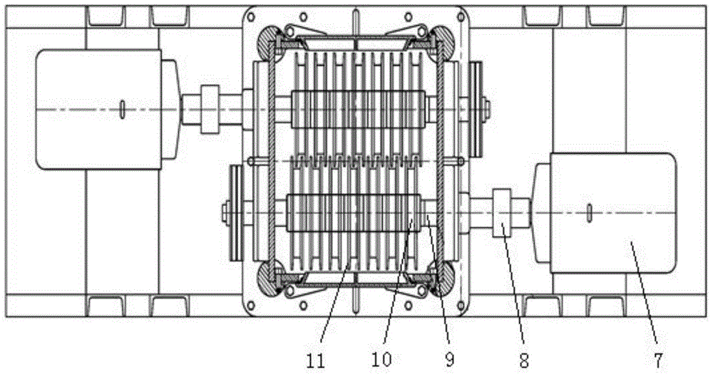
[0027] Referring to the accompanying drawings, the present invention is implemented in this way, a sludge powder mixer, which includes a motor A1, a worm gear reducer 2, a coupling C3, a drum shaft 4, a drum 5, a chassis 6, a motor B7, a shaft coupling Device D8, driving rotor shaft 9, driving rotor 10, powder mixing knife 11, pulley 12, belt 13, frame 14, driven rotor 16 and driven rotor shaft 17; the cabinet 6 is provided with a For the parallel roller shafts 4, a pair of parallel driven rotor shafts 17 and a pair of parallel driving rotor shafts 9, a belt 13 is used for transmission between the upper and lower adjacent driven rotor shafts 17 and the driving rotor shafts 9; 5 is set on the drum shaft 4, and one end of the drum shaft 4 is connected to the motor A1 through the coupling C3 and the worm gear reducer 2 in sequence. The motor A1 is set on the frame 14 and drives the two drums 5 to rotate in opposite directions And the upper end points of the two rollers all move t...


PUM


Abstract

A sludge powder mixer, which includes a motor A, a worm gear reducer, a coupling C, a drum shaft, a drum, a chassis, a motor B, a coupling D, a driven rotor shaft, a driven rotor, and a powder mixing knife , pulley, belt, frame, driving rotor, driving rotor shaft, a pair of parallel roller shafts, a pair of parallel driven rotor shafts and a pair of parallel driving rotor shafts are arranged in the cabinet from top to bottom, adjacent to each other up and down Belt transmission is adopted between the driven rotor shaft and the driving rotor shaft; the motor A is set on the frame and drives the rollers to run in opposite directions at low speed; the motor B is set on the frame and drives the driving rotor to run in opposite directions at high speed; the driven rotor and the There are several powder mixing knives on the active rotor and they are installed horizontally and / or up and down; it has the functions of rolling, crushing, mixing, throwing, etc., and can quickly and conveniently process sludge materials; it is widely used in urban sewage Used in conjunction with mud treatment.

Description

technical field [0001] The invention relates to a sludge powder mixer. Background technique [0002] With the continuous expansion of the city scale, the environmental problems caused by the sludge after urban sewage treatment have become increasingly prominent. In the composting treatment of urban sludge aerobic fermentation, it is necessary to use sludge, conditioners, and return materials in a set proportion The technical requirements of sludge aerobic fermentation can be better met only after being stirred by a machine; due to the physical and chemical characteristics of sludge and the process of stacking and storage, impurities are easily mixed in, which is not conducive to the operation of the general pulverizer, and the mixture formed by general pulverization and mixing It does not meet the technical requirements of aerobic fermentation, and anaerobic fermentation is formed in the process of aerobic fermentation, which produces stench and pollutes the environment; whi...

Claims


Application Information

Patent Timeline
Patent Type & Authority Patents(China)
IPC IPC(8): B02C18/14C02F11/00B01F13/10B02C18/24
Inventor 易庆国秦国春罗志诚
Owner HUNAN JIUFANG ENVIRONMENTAL PROTECTION MACHINERY
Why Eureka
Try Eureka