Check patentability & draft patents in minutes with Patsnap Eureka AI!

Planar array antenna setting method oriented at wireless energy transmission system

A planar array antenna and wireless energy transmission technology, which is applied in the directions of antenna arrays, antennas, and electrical components that are powered independently, can solve the problems of small excitation amplitude, difficulty in implementation, and low utilization of array apertures, and achieve low sidelobe currents. The effect of flatness, reduced complexity, and easy engineering realization

Inactive Publication Date: 2015-09-16
XIDIAN UNIV
View PDF0 Cites 8 Cited by
  • Summary
  • Abstract
  • Description
  • Claims
  • Application Information

AI Technical Summary

Problems solved by technology

First, in actual engineering, there are different degrees of difficulties in the realization of beamforming networks with "approximate Gaussian" excitation and "isosceles trapezoidal" excitation
Second, the excitation amplitude of the array elements in the edge area of ​​the array is relatively small compared to the excitation amplitude of the array elements in the center, resulting in low utilization of the array aperture

Method used


Image

  • Planar array antenna setting method oriented at wireless energy transmission system
  • Planar array antenna setting method oriented at wireless energy transmission system
  • Planar array antenna setting method oriented at wireless energy transmission system

Examples


specific Embodiment 1

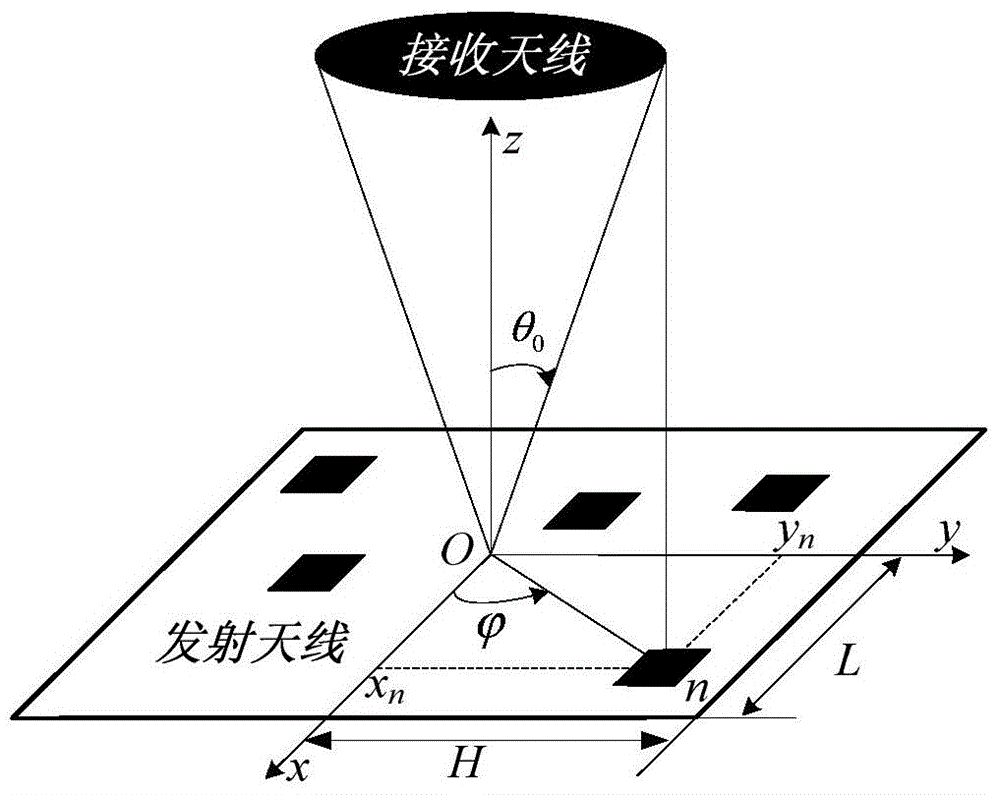
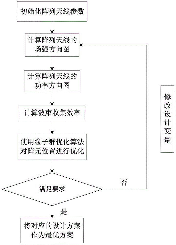
[0058] Such as figure 1 and figure 2 As shown, a planar array antenna array method for a wireless energy transmission system includes the following steps:

[0059] (1) Calculate the field strength pattern of the array antenna

[0060] If the array antenna has 4N array elements and is located in the xoy plane, the positions of all array elements are symmetrical about the x-axis and y-axis and each array element is isotropic, the field strength pattern F(u,v) of the array antenna is according to Formula (1-1) yields:

[0061]

[0062] where I n , and (x n ,y n ) are the excitation amplitude, phase and position coordinates of the nth array element respectively; k = 2 π λ , λ is the antenna operating wavelength, θ and are the elevation angle and azimuth angle of the observation point, j is the imaginary unit, k represents the wave number;

[0063] If the excit...

specific Embodiment 2

[0093] A planar array antenna array method for a wireless energy transmission system, comprising the following steps:

[0094] (1) Calculate the field strength pattern of the array antenna

[0095] If the array antenna has 4N array elements and is located in the xoy plane, the positions of all array elements are symmetrical about the x-axis and y-axis and each array element is isotropic, the field strength pattern F(u,v) of the array antenna is according to Formula (1-1) yields:

[0096]

[0097] where I n , and (x n ,y n ) are the excitation amplitude, phase and position coordinates of the nth array element respectively; λ is the antenna operating wavelength, θ and are the elevation angle and azimuth angle of the observation point, j is the imaginary unit, k represents the wave number;

[0098] If the excitations of all elements of the array antenna are evenly distributed without loss of generality, then I n = 1, Then formula (1-1) can be simplified as:

...


PUM


Abstract

The invention relates to a planar array antenna setting method oriented at a wireless energy transmission system. The method comprises the following steps: (1), calculating a field intensity directional diagram of an array antenna; (2), calculating a power directional diagram of the array antenna; (3), calculating a wave beam collection efficiency; (4), according to an optimization model, carrying out optimization on an array element position by using a particle swarm optimization algorithm; (5), carrying out the optimization at the step (4) by using the particle swarm optimization algorithm with the population size of 100, the evolution algebra of 2000, the inertia weight reducing linearly from 0.9 to 0.4 with the evolution algebra, and the accelerated factor of 2; and (6), determining whether the optimized wave beam collection efficiency meets the requirement. According to the invention, the method has the following beneficial effects: firstly, complexity of network forming by the array antenna wave beams can be reduced and the engineering realization becomes easy; and secondly, the wave beam collection efficiency is high and the minor lobe level is low.

Description

technical field [0001] The invention belongs to the technical field of antennas, and in particular relates to a planar array antenna arrangement method for a wireless energy transmission system. Background technique [0002] Wireless Power Transmission (Wireless Power Transmission) is a new technology with broad application prospects that transmits energy from one point (one area) to another point (another area) in the form of microwaves without using transmission cables. This technology can be used to power stationary systems such as cars, mobile phones, etc. and mobile systems such as drones, airships, etc. [0003] In addition, an important potential application object of wireless energy transmission is a space solar power station (Space Solar Power Satellite). The space solar power station is proposed on the basis of wireless energy transmission technology, specifically refers to the power system that collects solar energy through concentrators in space, then converts s...

Claims


Application Information

Patent Timeline
IPC IPC(8): H01Q21/06H01Q3/00
Inventor 李勋周金柱段宝岩黄进杨阳张逸群范健宇
Owner XIDIAN UNIV
Features
  • R&D
  • Intellectual Property
  • Life Sciences
  • Materials
  • Tech Scout
  • Unparalleled Data Quality
  • Higher Quality Content
  • 60% Fewer Hallucinations
Learn More