
Quench tube for polymer fiber extrusion

A technology of cooling pipes and polymers, which is applied in fiber processing, complete sets of equipment for the production of artificial threads, filtration and separation, etc., can solve the problems of unsatisfactory air distribution in cooling pipes, and achieve excellent cooling flow uniformity and excellent cooling The effect of flow distribution uniformity

Inactive Publication Date: 2015-09-16
NV BEKAERT SA
View PDF15 Cites 0 Cited by
  • Summary
  • Abstract
  • Description
  • Claims
  • Application Information

AI Technical Summary

Problems solved by technology

The problem with the cooling tubes of the prior art is that the cooling tubes are not ideal in terms of uniformity of air distribution

Method used


Image

  • Quench tube for polymer fiber extrusion

Examples


Embodiment Construction

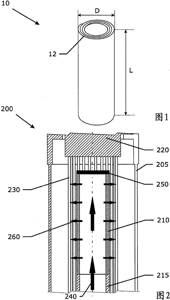
[0052] figure 1 An example of a cooling pipe 10 according to the present invention is shown. L represents the length of the cooling pipe, for example 150mm, and D is its outer diameter. It is manufactured by circular winding (coiling) of an unsintered non-woven stainless steel fiber web around a core of suitable diameter, for example around a spool. Carded, air-laid or wet-laid nonwoven stainless steel fiber webs can advantageously be used. The mesh is wound in order to obtain multiple layers 12 until the desired diameter for the cylindrical shape of the coiled elongated metal fiber structure of the cooling tube is obtained. The number of layers used helps to obtain a uniform cooling air distribution on the outflow surface of the cooling tubes. The metal fibers of such a coiled elongated metal fiber structure are then bonded metallurgically, for example by sintering or by welding, without using additional bonding material. Such welding can be performed, for example, by cap...


PUM

PropertyMeasurementUnit
lengthaaaaaaaaaa
lengthaaaaaaaaaa

Abstract

The quench tube comprises a cylindrical wall through which quenching air flows when the quench tube is in use. The cylindrical wall comprises metal fibers in a nonwoven fiber structure. The metal fibers are bonded to each other at contacting points by means of metallurgical bonds thereby forming a three dimensionally bonded fiber structure.

Description

technical field [0001] The present invention relates to the field of cooling pipes used in the extrusion of polymer fibers or filaments and to a method of manufacturing such cooling pipes. Background technique [0002] The use of cooling pipes in polymer fiber extrusion is known, for example in extrusion processes for the manufacture of POY (Partially Oriented Yarn) or FDY (Fully Drawn Yarn) polyester multifilament yarns. After extrusion, the fibers or filaments pass through a cooling zone comprising one or more cooling tubes. Air is directed through the walls of the cooling tube (inside-out or outside-in), which air cools and (sometimes also) draws the fibers or filaments. [0003] Different types of cooling tubes exist and have been disclosed. [0004] GB1382499 proposes cooling pipes made of porous material such as ceramic or sintered metal powder. Sintered bronze powder is used as a specific example for cooling tubes. [0005] EP1491663 cites cooling pipes made of mu...

Claims


Application Information

Patent Timeline
Patent Type & Authority Applications(China)
IPC IPC(8): D01D5/088B01D39/20B22F3/00D01D13/02
CPCD01D13/02B22F5/106B22F2005/103D01D5/088B22F3/002B01D39/2041B01D39/2044B23K9/1081B23K31/027
Inventor F·韦沙瓦S·万登迪克M·源J·德贝尔德梅克
Owner NV BEKAERT SA
Learn More