Explosive rotating machine for press fitting production line

A technology of press-fitting production line and powder spinning machine, which is applied in the direction of nailing tools and manufacturing tools, can solve the problems of small number of nail shooting bullets, low work efficiency, and impermeable drying of explosives, so as to reduce production costs and reduce a Process, the effect of facilitating the organization of production

Active Publication Date: 2015-09-23
CHONGQING INST OF MECHANICAL & ELECTRICAL ENG
6 Cites 0 Cited by

AI-Extracted Technical Summary

Problems solved by technology

Initially, nail-shooting bombs were assembled by press-fitting. This method mainly has the following defects: 1. The consumption of explosives is large; 2. Because the explosives need to be dried, energy consumption is required; 3. Explosives often appear during the manufacturing process. If the drying is impermeable, this will result in a high scrap rate
The above-mentioned medicine spinning machine of the press-packing production line mainly has the following defects: 1. Since one motor drives one medi...

Abstract

The invention discloses an explosive rotating machine for a press fitting production line. A motor is mounted on a mounting seat; a group of supporting plates are overlapped on the bottom surface of the mounting seat in sequence; the supporting plates are fixedly connected with the mounting seat by a group of positioning columns; the motor drives three level gear drive mechanisms which are respectively a first level gear drive mechanism, a second level gear drive mechanism and a third level gear drive mechanism; the first level gear drive mechanism is provided with four output ends; the second level gear drive mechanism is provided with four input ends and sixteen output ends; and the third level gear drive mechanism is provided with sixteen input ends and one hundred and sixty one output ends. The invention has the advantages that the structure is reasonable and compact; the drive is reliable; the size is small; the weight is light; the energy consumption is low; one hundred and sixty one nail shooting pills can be mounted in a rotating way at a time, so that the explosive rotation efficiency can be greatly improved; secondary plate installation is not needed any more, so that one working procedure is omitted, and production organization is facilitated and the production cost can be reduced.

Application Domain

Technology Topic

Image

  • Explosive rotating machine for press fitting production line
  • Explosive rotating machine for press fitting production line
  • Explosive rotating machine for press fitting production line

Examples

  • Experimental program(1)

Example Embodiment

[0018] The present invention will be further described below in conjunction with the drawings and embodiments:
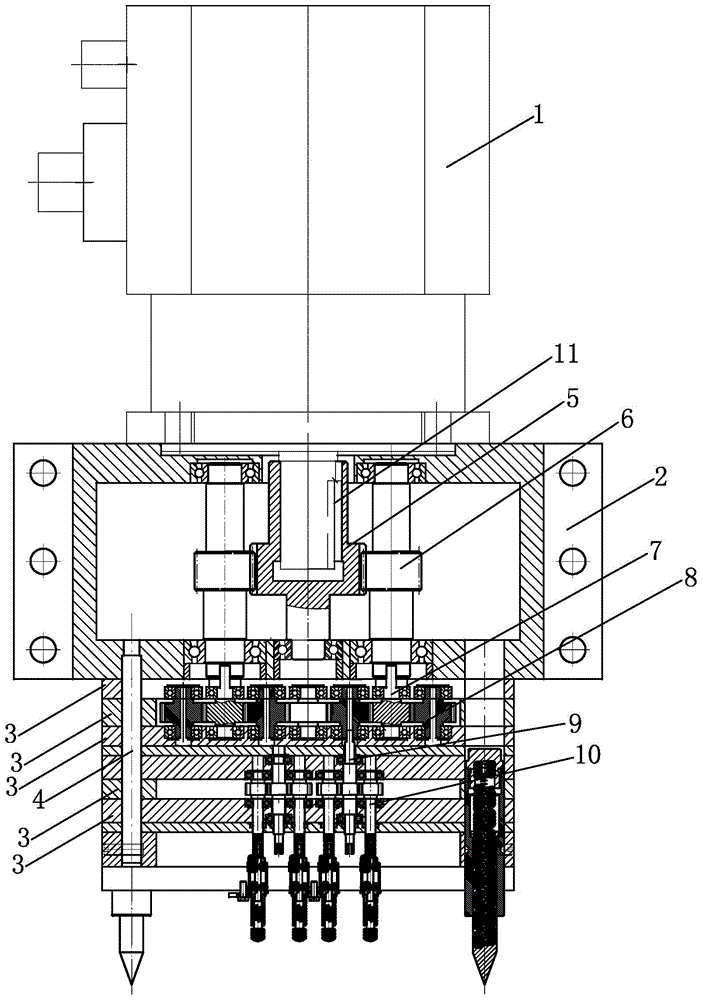
[0019] Such as figure 1 , 2 , 3 and 4, a press-fitting production line spinner, mainly composed of a motor 1, a mounting base 2, a support plate 3, a positioning column 4 and a three-stage gear transmission mechanism. The motor 1 is mounted on a mounting base 2, and a set of support plates 3 are sequentially overlapped on the bottom surface of the mounting base 2, and these support plates 3 are connected and fixed to the mounting base 2 by a set of positioning columns 4. The motor 1 drives a three-stage gear transmission mechanism, which are respectively a first-stage gear transmission mechanism, a second-stage gear transmission mechanism and a third-stage gear transmission mechanism.
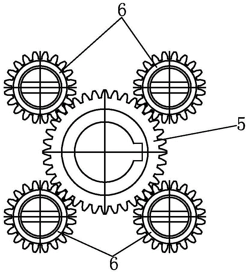
[0020] Such as figure 1 , 2 As shown, the first-stage gear transmission mechanism is mainly composed of a first-stage driving gear shaft 5, a first-stage driven gear shaft 6 and a key 11, wherein the upper end of the first-stage driving gear shaft 5 and the output shaft of the motor 1 The lower end is coaxially connected, and the lower end of the first-stage driving gear shaft 5 is supported on the mounting seat 2 through a bearing. Preferably, the lower end of the output shaft of the motor 1 is inserted into the blind hole at the upper end of the first-stage driving gear shaft 5, and the insertion part of the output shaft of the motor 1 is connected to the first-stage driving gear shaft 5 through a flat key 11.
[0021] The number of the first-stage driven gear shafts 6 is four, and the four first-stage driven gear shafts 6 are evenly distributed along the circumferential direction of the first-stage driving gear shaft 5. The teeth on the first-stage driven gear shaft 6 The shape meshes with the tooth shape on the first-stage driving gear shaft 5. In addition, the tooth profile diameters on the four first-stage driven gear shafts 6 are equal and smaller than the tooth profile diameter on the first-stage driving gear shaft 5, so that the rotational speeds of the four first-stage driven gear shafts 6 are equal. The upper and lower ends of the four first-stage driven gear shafts 6 are respectively supported on the mounting seat 2 through bearings. The lower ends of the four first-stage driven gear shafts 6 are all n-shaped connecting parts, thus forming four The output ends, these 4 output ends are the output ends of the first-stage gear transmission mechanism, and these 4 output ends are also the input ends of the second-stage gear transmission mechanism at the same time.
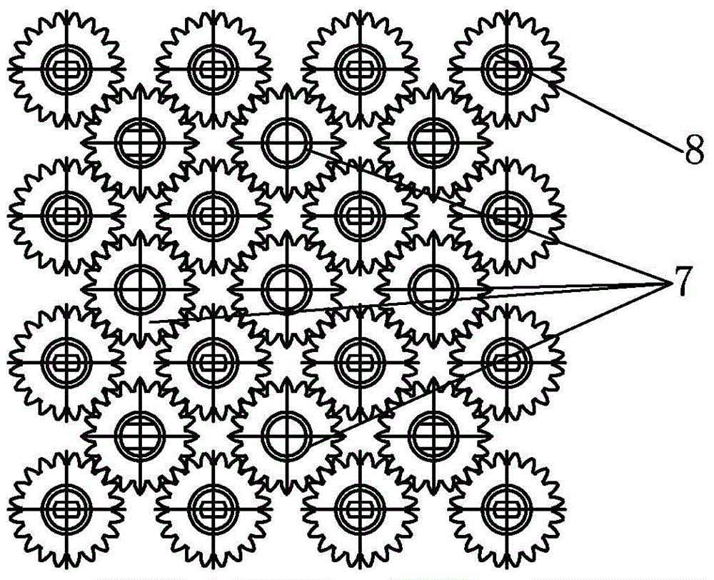
[0022] Such as figure 1 , 3 As shown, the second-stage gear transmission mechanism is mainly composed of a second-stage driving gear shaft 7 and a second-stage driven gear shaft 8. Among them, the number of the second-stage driving gear shafts 7 is 4, and the positions of these 4 second-stage driving gear shafts 7 correspond to the first-stage driven gear shafts 6 one-to-one, and the upper end of each second-stage driving gear shaft 7 The protruding parts of the upper part are respectively locked into the n-shaped connecting parts of the lower ends of the four first-stage driven gear shafts 6, so as to accept the power output by the first-stage gear transmission mechanism.
[0023] The number of the second-stage driven gear shafts 8 is 21. These second-stage driven gear shafts 8 and the second-stage driving gear shafts 7 are arranged in two rectangular arrays, and the order of the first rectangular array is 4 *4, the order of the second rectangular array is 3*3. In addition, all the elements of the first rectangular array are the second-level driven gear shafts 8, and the elements in the second rectangular array have both the second-level driven gear shafts 8 and the second-level driving gear shafts 7. Each row of elements in the second rectangular array is located between the elements of two adjacent rows in the first rectangular array, and the tooth profile on the two adjacent second-stage driven gear shafts 8 and the second-stage driven gear shaft 8 and The teeth on the second-stage driving gear shaft 7 are respectively meshed with each other. The tooth profile diameters on the two gear shafts in the second-stage gear transmission mechanism are equal, so that the speeds of the second-stage driving gear shaft 7 and the second-stage driven gear shaft 8 are equal, and the first-stage driven gear shaft 6 The speed is less than the speed of the two gear shafts in the second-stage gear transmission mechanism.
[0024] The upper and lower ends of the second-stage driving gear shaft 7 and the second-stage driven gear shaft 8 are respectively supported on the corresponding support plate 3 through bearings. In addition, the lower ends of the 16 second-stage driven gear shafts 8 of the first rectangular array are respectively n-shaped connecting parts, thereby forming 16 output ends. These 16 output ends are the output ends of the second-stage gear transmission mechanism. These 16 output ends are also the input ends of the third-stage gear transmission mechanism.
[0025] Such as figure 1 , 4 As shown, the third-stage gear transmission mechanism is mainly composed of a third-stage driving gear shaft 9 and a third-stage driven gear shaft 10. Among them, the number of third-stage driving gear shafts 9 is 16, and the positions of these third-stage driving gear shafts 9 correspond to the 16 second-stage driven gear shafts 8 of the first rectangular array one-to-one, and 16 third-stage driven gear shafts 8 The protrusions at the upper end of the primary driving gear shaft 9 are respectively clamped into the n-shaped connecting parts of the secondary driven gear shaft 8 in the first rectangular array, so as to access the power output by the secondary gear transmission mechanism.
[0026] The number of the third-stage driven gear shafts 10 is 145. These third-stage driven gear shafts 10 and the third-stage driving gear shafts 9 are arranged in two rectangular arrays, and the order of the first rectangular array is 9*9, the order of the second rectangular array is 8*10. Each row of elements of the second rectangular array is located between two adjacent rows of elements in the first rectangular array, and the tooth profile on the two adjacent third-stage driven gear shafts 10 and the third-stage driven gear shaft 10 meshes with the teeth on the third-stage driving gear shaft 9 respectively. The tooth profile diameters on the two gear shafts in the third-stage gear transmission mechanism are equal, so that the rotation speeds of the third-stage driving gear shaft 9 and the third-stage driven gear shaft 10 are equal, and the gear shaft in the second-stage gear transmission mechanism The speed of is smaller than the speed of the gear shaft in the third-stage gear transmission mechanism.
[0027] The upper and lower ends of the third-stage driving gear shaft 9 and the third-stage driven gear shaft 10 are respectively supported on the support plate through bearings, and all the third-stage driving gear shafts 9 and third-stage driven gear shafts 10 The lower end parts are respectively n-shaped output parts, and the n-shaped output parts are used to connect the stirring head, thereby forming 161 output ends.
[0028] It should be pointed out that figure 1 The joints of the first and second gear transmission mechanisms in the middle table style and the joints of the second and third gear transmission mechanisms are not completely expressed due to the limitation of the cross-sectional angle and the omission of drawing. figure 2 Except for the four second-stage driving gear shafts 7, all the remaining are second-stage driven gear shafts 8.
[0029] The above are only the preferred embodiments of the present invention and are not limited to the present invention. Any modification, equivalent replacement and improvement made within the spirit and principle of the present invention shall be included in the present invention. Within the scope of protection.

PUM

no PUM

Description & Claims & Application Information

We can also present the details of the Description, Claims and Application information to help users get a comprehensive understanding of the technical details of the patent, such as background art, summary of invention, brief description of drawings, description of embodiments, and other original content. On the other hand, users can also determine the specific scope of protection of the technology through the list of claims; as well as understand the changes in the life cycle of the technology with the presentation of the patent timeline. Login to view more.

Similar technology patents

Laser beam coupling output device for high-power semiconductor

InactiveCN102012567AReasonable structureReduce the difficulty of machiningPolarising elementsSemiconductor laser theoryPower semiconductor device
Owner:BEIJING UNIV OF TECH

Classification and recommendation of technical efficacy words

  • Reliable transmission
  • Reasonable structure

Switch cabinet contact temperature monitoring and alarming system

ActiveCN101055209AReliable transmissionProtection against switchgear failureThermometers using electric/magnetic elementsUsing electrical meansData transmissionPower supply unit
Owner:山东惠工电气股份有限公司

Remote Patient Management Device and Method

ActiveUS20130169432A1Reliable transmissionLocal control/monitoringTelemedicineChronic diseaseDisease cause
Owner:TURKCELL TEKNOLOJI ARASTIRMA & GELISTIRME AS

A ceramic insulator device for high voltage capacitor

InactiveCN101546636ALow manufacturing costReasonable structureSuspension/strain insulatorsHigh voltage capacitorsEngineering
Owner:王海龙
Why Eureka
Try Eureka