Phase-controlled valve

A technology of phase control and flow limiting valve, which is applied in the direction of wellbore/well valve device, production fluid, wellbore/well components, etc. It can solve the problems of ICD water control tool failure water cut, etc., and eliminate the influence of annular flow , enhance oil recovery, and delay the effect of water ridges

Inactive Publication Date: 2015-09-23
SOUTHWEST PETROLEUM UNIV
View PDF7 Cites 5 Cited by
  • Summary
  • Abstract
  • Description
  • Claims
  • Application Information

AI Technical Summary

Problems solved by technology

[0003] The purpose of the present invention is to overcome the shortcomings of the prior art, solve the practical problems that the existing ICD water control tools fail after water breakthrough in horizontal wells and the current high water content of most horizontal wells, and provide a tool that can meet the initial completion production requirements of horizontal wells. A phase control valve that meets the requirements of liquid profile balance and can automatically limit water production in oilfield horizontal wells during high water cut periods

Method used


Image

  • Phase-controlled valve
  • Phase-controlled valve
  • Phase-controlled valve

Examples


Embodiment Construction

[0017] The present invention will be further described below in conjunction with accompanying drawing, protection scope of the present invention is not limited to the following:

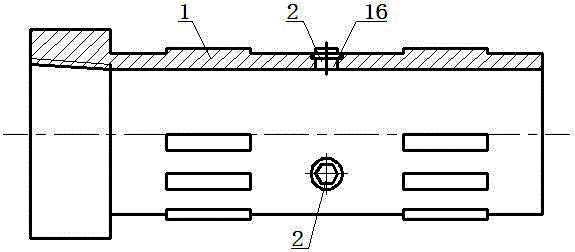
[0018] like figure 1 As shown, the phase control valve includes a base pipe 1 and a restrictor valve 2 threaded with the base pipe 1 .

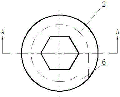
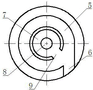
[0019] like figure 2 , image 3 , Figure 4 As shown, the flow limiting valve 2 includes an upper end cover 3 and a lower end cover 4, the lower end cover 4 is provided with a liquid inlet 6 and an annular flow channel 5 communicating with the liquid inlet 6, the annular flow channel 5 is arc-shaped, Thus, the fluid guided into the annular flow passage 5 flows in a circular arc shape, and the annular flow passage 5 encloses the control chamber 7, and the side wall of the control chamber 7 is provided with a communication ring flow passage 5 and the control chamber. The flow channel 9 of the chamber 7, the opening of the flow channel 9 faces the liquid inlet 6, ...


PUM


Abstract

The invention discloses a phase-controlled valve. The phase-controlled valve comprises a base pipe (1), flow limiting valves (2) are mounted on the base pipe (1), a lower end cover (4) of each flow limiting valve (2) is provided with an annular flow passage (5) and a control chamber (7), the side wall of the control chamber (7) is provided with a sluice (9) through which the annular flow passage (5) and the control chamber (7) are communicated, and the base pipe (1) is provided with a base pipe liquid inlet (10) communicated with a nozzle (8) of the control chamber (7). The phase-controlled valve has the advantages that fluids can be distinguished, oil and water can be separated automatically, water output is limited to balance profiles and eliminate heel effects, annular flow influences are eliminated, productive life of an oil-gas well can be prolonged, recovery efficiency of a control reservoir of a horizontal well can be improved beneficially, and the phase-controlled valve is applicable to edge/bottom water reservoirs high in anisotropism.

Description

technical field [0001] The invention relates to an automatic water control tool for oil exploitation, in particular to an automatic flow-limiting phase control valve. Background technique [0002] As a high-efficiency development method with fewer wells and high yield, horizontal wells have been widely used in the development of thin-bed reservoirs, bottom water reservoirs, fractured reservoirs, heavy oil reservoirs, marine shallow and deep-water reservoirs, and unconventional reservoirs . However, the problems of horizontal wells and their complex structure wells in the production process of different types of reservoirs (especially edge / bottom water reservoirs) are becoming more and more prominent, mainly manifested in the rapid advance of edge / bottom water ridges, and the rapid rise of water cut in horizontal wells. It is very difficult to find water and block water, which has seriously affected the comprehensive benefits of horizontal well development and has become a t...

Claims


Application Information

Patent Timeline
Patent Type & Authority Applications(China)
IPC IPC(8): E21B34/06E21B43/38
Inventor 李海涛阳明君王永清朱世琰蒋睿
Owner SOUTHWEST PETROLEUM UNIV
Why Eureka
Try Eureka