One-piece sub-tank structure and oil pressure buffer using it

A technology of oil pressure buffer and auxiliary oil tank, applied in the field of oil pressure buffer, can solve problems such as time-consuming and money-consuming, high maintenance cost, weakening, etc., and achieve the effect of convenient oil filling, prolonging service life, and reducing use and maintenance cost.

Active Publication Date: 2017-03-01
FENGHUA CITY TRANSIENT FORCE HYDRAULIC BUFFER
View PDF12 Cites 0 Cited by
  • Summary
  • Abstract
  • Description
  • Claims
  • Application Information

AI Technical Summary

Problems solved by technology

[0003] Due to the frequent reciprocation of the piston rod of the above-mentioned oil pressure buffer or oil pressure stabilizer, after a long time of use, the piston rod will take the hydraulic oil in the internal pressure cylinder out of the oil seal end. If the oil volume of the internal pressure cylinder is reduced, there will be problems such as unstable speed or weakened cushioning force. It needs to be repaired and refilled with oil. This will bring inconvenience to the production and users of the oil pressure buffer or oil pressure stabilizer, and consume a lot of time and money. , higher maintenance cost

Method used


Image

  • One-piece sub-tank structure and oil pressure buffer using it
  • One-piece sub-tank structure and oil pressure buffer using it
  • One-piece sub-tank structure and oil pressure buffer using it

Examples


Embodiment 1

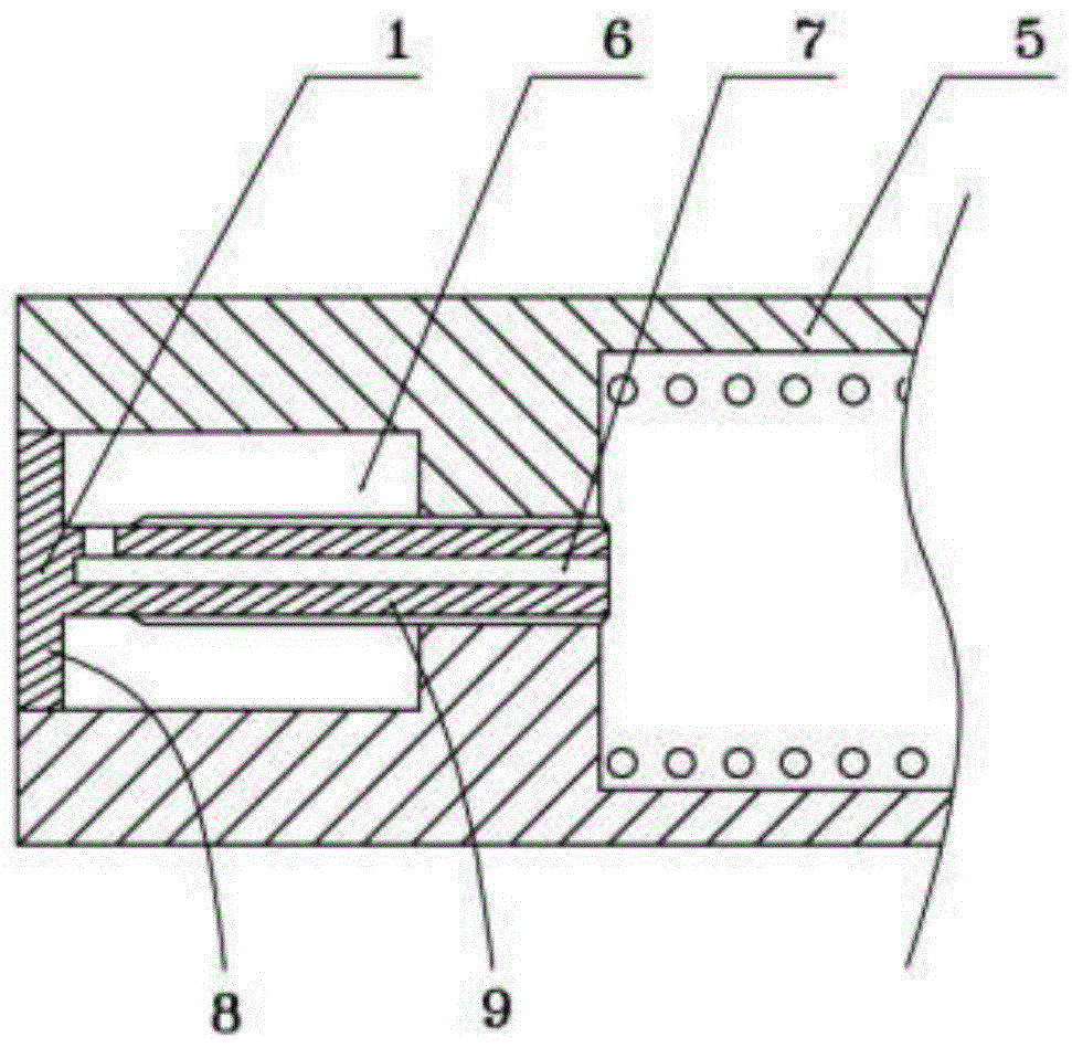
[0028] Embodiment 1, with reference to figure 1 A conjoined sub-tank structure is shown, and the oil pressure buffer using the conjoined sub-tank structure is as follows: Figure 5 As shown, the cylinder body 5 comprising the oil pressure buffer is provided with an accommodating chamber at the end of the cylinder body 5 away from the piston rod, and an oil tank rear cover 1 threadedly connected with the cylinder body 5 is arranged in the accommodating chamber; When the cover 1 is screwed to the cylinder body 5, the rear cover 1 of the fuel tank cooperates with the cylinder body 5 so that the accommodating cavity forms a closed oil storage chamber 6, and the rear cover 1 of the fuel tank also has a Connected oil delivery channel 7.

[0029] The cylinder body 5 is provided with a threaded through hole 10 for communicating the accommodating cavity with the interior of the cylinder body 5. The fuel tank back cover 1 includes a base 8 and a threaded connection portion 9 extending ...

Embodiment 2

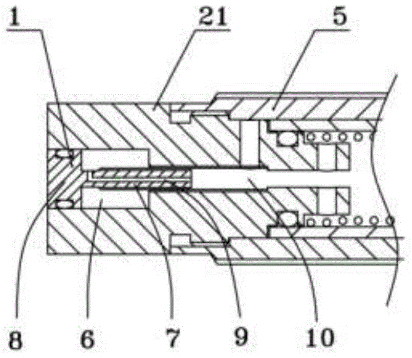
[0030] Embodiment 2, with reference to figure 2 A conjoined sub-tank structure is shown, and the oil pressure buffer using the conjoined sub-tank structure is as follows: Figure 6 As shown, the cylinder body 5 comprising the oil pressure buffer is provided with an end cap 21 at the end far away from the piston rod, and the end cap 21 is threadedly connected with the cylinder body 5, and the end cap 21 is provided with an accommodation chamber, and A fuel tank rear cover 1 threadedly connected with the end cap 21 is arranged in the storage chamber; when the fuel tank rear cover 1 and the end cap 21 are screwed together, the fuel tank rear cover 1 and the end cap 21 cooperate so that the accommodating cavity forms an airtight oil storage chamber 6. The oil tank rear cover 1 is also provided with an oil delivery channel 7 connecting the oil storage chamber 6 with the inside of the cylinder body 5 .

[0031]The end cover 21 is provided with a threaded through hole 10 for commun...

Embodiment 3

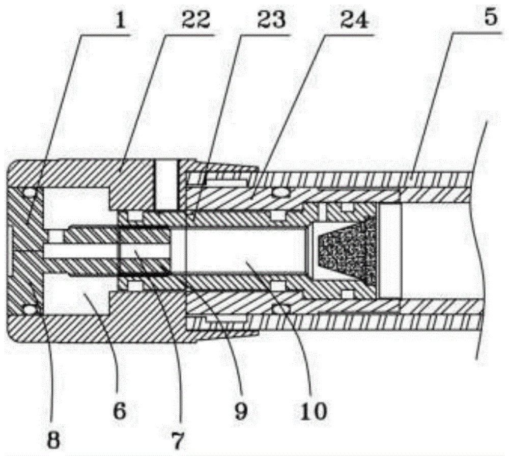
[0032] Embodiment 3, with reference to image 3 A conjoined sub-tank structure is shown, and the oil pressure stabilizer using the conjoined sub-tank structure is as follows Figure 7 and Figure 8 shown, where Figure 8 In order to use the air return type oil pressure stabilizer with the conjoined auxiliary oil tank structure, the cylinder body 5 of the oil pressure buffer is included, and the end of the cylinder body 5 away from the piston rod is also provided with a regulating valve. The regulating valve includes an regulating nut 22, a valve The valve core 23 and the valve housing 24, the valve housing 24 is connected with the cylinder body 5, the adjusting nut 22 is connected with the valve core 23, the valve core 23 can rotate relative to the valve housing 24, and the valve core 23 and the valve housing 24 are provided with relatively matching oil holes , by rotating the spool 23 to adjust the diameter of the oil hole, so as to realize the adjustment of the speed and p...


PUM


Abstract

The invention relates to a connected auxiliary oil tank structure. The connected auxiliary oil tank structure comprises a cylinder body of an oil pressure buffering device, the end, far away from a piston rod, of the cylinder body is provided with a containing cavity, and an oil tank rear cover in threaded connection with the cylinder body is arranged in the containing cavity. When the oil tank rear cover is rotationally connected with the cylinder body, the oil tank rear cover is matched with the cylinder body so that the containing cavity can form a closed oil storing cavity, and the oil tank rear cover is further provided with an oil delivery channel enabling the oil storing cavity to be communicated with the interior of the cylinder body. According to the connected auxiliary oil tank structure, hydraulic oil reserved in the oil storing cavity is supplemented to the interior of the cylinder body of the oil pressure buffering device by screwing in the oil tank rear cover so that it can be guaranteed that the oil pressure buffering device can work for a long time at the optimal stable speed or in a buffering state, after-sales services and maintenance of the oil pressure buffering device are avoided for a longer using time, the service life of the oil pressure buffering device is substantially prolonged, and using and maintaining cost is reduced.

Description

technical field [0001] The invention relates to the technical field of oil pressure buffers, in particular to a connected auxiliary oil tank structure and an oil pressure buffer using the same. Background technique [0002] Oil pressure buffer (speed stabilizer, damper) is a hydraulic device that converts impact kinetic energy into hydraulic oil heat energy, realizes linear deceleration of objects, and finally stops smoothly. It is usually widely used in automatic machinery such as manipulators, pneumatic cylinders, speed-adjustable drilling machines, grinding machines, cutting machines, glasses machinery, drilling machinery, woodworking machinery, lock making equipment, watch machinery, cutting machines, etc. See the oil pressure shock absorber disclosed by the patent announcement number CN204140749U, the oil pressure shock absorber does not have pressure adjustment, and includes an external pressure cylinder, an internal pressure cylinder, a pressure storage sponge, a rear...

Claims


Application Information

Patent Timeline
Patent Type & Authority Patents(China)
IPC IPC(8): F16F9/32F16F9/34F15B1/26
CPCF16F9/32
Inventor 胡益
Owner FENGHUA CITY TRANSIENT FORCE HYDRAULIC BUFFER
Why Eureka
Try Eureka