Ball screw servo loading test device based on hydraulic servo system

A technology of loading test device and hydraulic servo system, applied in the direction of machine gear/transmission mechanism testing, etc., can solve the problems of high price, long loading test device, inability to display and control the load in real time, etc., and achieve convenient load adjustment and simple structure. , the effect of easy adjustment

Inactive Publication Date: 2015-09-23
NANJING UNIV OF SCI & TECH
View PDF6 Cites 8 Cited by
  • Summary
  • Abstract
  • Description
  • Claims
  • Application Information

AI Technical Summary

Problems solved by technology

[0003] The experimental research on the ball screw needs to load the ball screw according to the working conditions. Most of the traditional ball screw test devices use passive loading methods such as counterweight friction or spring traction, and the load cannot be displayed and controlled in real time during the test. The loading method can no longer meet the requirements of the test device for variable load simulation
[0004] And the current ball screw test device is mainly aimed at testing a certain performance of the ball screw, and the loading method is not suitable for other performance tests, and it takes a long time to design a ball screw servo loading test device, and the price is expensive

Method used


Image

  • Ball screw servo loading test device based on hydraulic servo system
  • Ball screw servo loading test device based on hydraulic servo system
  • Ball screw servo loading test device based on hydraulic servo system

Examples


Embodiment

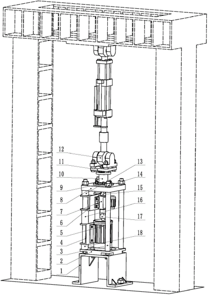
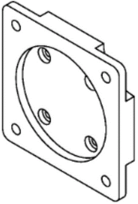
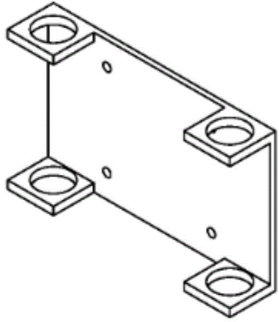
[0026] A ball screw servo loading test device based on a hydraulic servo system, comprising a floor base 1, a base plate 2 fixed on the floor base 1, a mounting seat 8 fixed on the top of the base plate 2 through a supporting steel pipe 3 in the vertical direction, and the base plate 2. There are four stepped holes in the middle and through holes at the four corners. The bottom plate 2 is fixed on the floor base 1 through the four stepped holes in the middle. The steel pipes 3 are installed vertically in the four corner through holes of the bottom plate 2 and fixed respectively, and are located above the bottom plate 2. The mounting base 8 is fixed on the other end of the four supporting steel pipes 3, and is fixed on the supporting steel pipes 3 by tightening the nuts 14. Above, the supporting steel pipe 3 plays the role of supporting the mounting seat 8, the structure of the motor fixing plate 4 is the same as that of the speed torque sensor fixing plate 6, and its holes are ...


PUM


Abstract

The invention discloses a ball screw servo loading test device based on a hydraulic servo system. The whole device has a vertical structure. A landing base is fixed on a pedestal or the ground, and a bottom plate is fixed on the landing base. Four supporting steel pipes are vertically fixed in the four corners of the bottom plate. An installing base is fixed at the upper ends of the four supporting steel pipes. A motor and a rotating speed torque sensor are installed on two of the supporting steel pipes. A rotating speed torque sensor shaft is respectively connected with a motor and a ball screw shaft. The nut of a ball screw is fixedly connected with a nut sleeve. The nut sleeve is installed in a rotation-limiting supporting base. The nut sleeve is connected with an electro-hydraulic servo actuator via an actuator connection plate. Active loading can be performed on the ball screw so that load adjustment is convenient, simulation of the working conditions of varied loads can be realized, the loads can be displayed and controlled in real time, and performance testing of the ball screw can also be performed.

Description

technical field [0001] The invention belongs to the technical field of ball screw loading tests, in particular to a ball screw servo loading test device based on a hydraulic servo system. Background technique [0002] Ball screw is a mechanical device that can convert rotary motion and linear motion. It has been widely used in industrial fields such as precision machine tools, oil drilling and scientific measurement. It has the characteristics of high precision, high efficiency, high rigidity and high load capacity. At present, the theoretical research on the ball screw at home and abroad has been relatively mature, and now it mainly focuses on the experimental research on the ball screw. With the application of ball screw more and more widely, its working conditions are more complicated. [0003] The experimental research on the ball screw needs to load the ball screw according to the working conditions. Most of the traditional ball screw test devices use passive loading m...

Claims


Application Information

Patent Timeline
Patent Type & Authority Applications(China)
IPC IPC(8): G01M13/02
Inventor 范云勋崔高尚张立柱徐令令罗相银
Owner NANJING UNIV OF SCI & TECH
Why Eureka
Try Eureka