Multipath magnetic circuit unit lamellar permanent-magnet linear oscillating motor

A technology of permanent magnet straight line and single piece, applied in the direction of magnetic circuit rotating parts, magnetic circuit shape/style/structure, electric components, etc., can solve the problems that affect the service life of the motor, the lead wire problem is difficult to solve, and the driving force is small. Achieve the effect of convenient load adjustment, convenient adjustment and simple production process

Inactive Publication Date: 2012-05-23
TECHNICAL INST OF PHYSICS & CHEMISTRY - CHINESE ACAD OF SCI
View PDF6 Cites 0 Cited by
  • Summary
  • Abstract
  • Description
  • Claims
  • Application Information

AI Technical Summary

Problems solved by technology

The moving coil linear oscillation motor is that the mover is composed of a coil, and the excitation is provided by another coil, or by a fixed permanent magnet component. The advantage of this type of motor is that it is easy to control the stroke, and there is no radial force and torque on the mover. There is no axial force at no-load, and there is no hysteresis loss, but the driving force is relatively small, and the lead wire problem is not easy to solve, which directly affects the service life of the motor, and due to the energy consumption caused by the coil energization, the efficiency is relatively low. lower

Method used


Image

  • Multipath magnetic circuit unit lamellar permanent-magnet linear oscillating motor
  • Multipath magnetic circuit unit lamellar permanent-magnet linear oscillating motor
  • Multipath magnetic circuit unit lamellar permanent-magnet linear oscillating motor

Examples


Embodiment 1

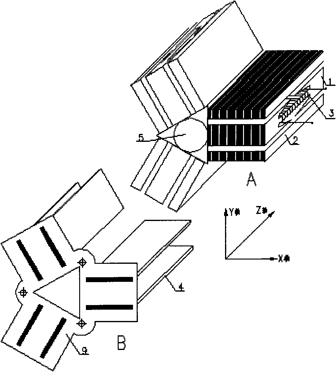
[0058] attached figure 1 It is a schematic diagram of the structure and principle of the multi-magnetic circuit unit (three magnetic circuit unit) chip permanent magnet linear oscillating motor of the present invention; the three magnetic circuit unit chip permanent magnet linear oscillating motor of this embodiment is composed of a stator part A and a mover part B , the stator part A includes:

[0059] A tubular cavity 5; the outer surface of the tubular cavity 5 is a regular trihedron; the size of the regular trihedron in the middle section of the outer surface of the tubular cavity 5 is smaller than the regular trihedron size of the two ends of the outer surface of the tubular cavity 5;

[0060] Three magnetic circuit units placed on the outer surface of the tubular cavity 5;

[0061] Each magnetic circuit unit includes:

[0062] An intermediate magnetic conductor 1; the intermediate magnetic conductor 1 has a longitudinal section in the form of Shaped magnetic conducto...

Embodiment 2

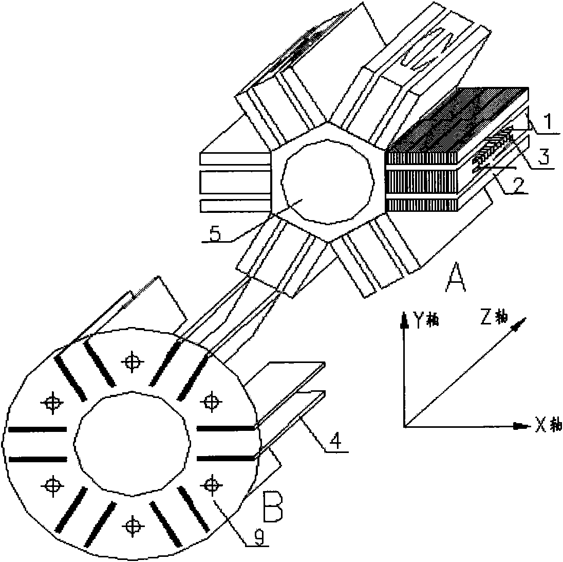
[0074] attached figure 2 It is a schematic diagram of the structure and principle of the multi-magnetic circuit unit (six magnetic circuit unit) chip type permanent magnet linear oscillating motor of the present invention; composition;

[0075] The stator part A includes:

[0076] A tubular cavity 5; the outer surface of the tubular cavity 5 is a regular hexahedron; the size of the regular hexahedron in the middle section of the outer surface of the tubular cavity 5 is smaller than the regular hexahedron of the two ends of the outer surface of the tubular cavity 5 size;

[0077] Six magnetic circuit units placed on the outer surface of the tubular cavity 5;

[0078] Each magnetic circuit unit includes:

[0079] An intermediate magnetic conductor 1; the intermediate magnetic conductor 1 is formed by a plurality of pieces The longitudinal section formed by stacking sheet-shaped magnetically permeable materials is Shaped magnetic conductor (made of stacked silicon steel ...


PUM


Abstract

The invention relates to a multipath magnetic circuit unit lamellar permanent-magnet linear oscillating motor comprising a stator part and a rotor part; the stator part comprises a tubular cavity and magnetic circuit units; the tubular cavity has outer surfaces in a regular polyhedron; the magnetic circuit units are arranged on the outer surfaces; each magnetic circuit unit comprises a middle magnetic conductor and two magnetic conductors, wherein the longitudinal section of the middle magnetic conductor is in an H shape, a column of the middle magnetic conductor is wound by a coil, the two magnetic conductors are arranged at both sides of the middle magnetic conductor, and a strip-shaped air gap is arranged between the middle magnetic conductor and each of the magnetic conductors; the rotor part comprises a plurality of lamellar permanent magnets and symmetrical type magnetic circuits, wherein the plurality of lamellar permanent magnets are vertically arranged on connecting pieces ina radial shape, are inserted into a rectangular hole positioned in the connecting piece positioned at one end of the tubular cavity and extend into a rectangular hole positioned in the connecting piece positioned at the other end of the tubular cavity; each magnetic circuit unit is positioned among the lamellar permanent magnets; the symmetrical type magnetic circuits are formed by symmetrically magnetizing the middle magnetic conductor and the magnetic conductors along the length direction of the middle magnetic conductor; the coil generates a magnetic field by being electrified with alternating current and forms a magnetic field with alternate positive and negative directions in the strip-shaped air gaps through the symmetrical type magnetic circuits; and the rotor does reciprocating oscillation motion along the length directions of the strip-shaped air gaps in the strip-shaped air gaps under the action of the magnetic field.

Description

technical field [0001] The invention relates to the field of linear motors. Background technique [0002] Linear oscillating motor refers to a motor that performs high-frequency reciprocating linear motion. As a kind of linear motor, it also has various advantages of linear motors, such as electric energy directly generates electromagnetic thrust, directly pushes the load to do linear motion, and does not need the conversion device of traditional rotary motor to convert rotation into linear motion, which improves the transmission Efficiency, reduced mechanical wear, etc. Linear oscillating motors are often used as driving mechanisms for small reciprocating compressors, sewing machines, electric hammer machines and other equipment due to the reciprocating oscillating motion of their movers. [0003] There are two main classifications of linear oscillating motors: linear induction oscillating motors and linear synchronous oscillating motors. Compared with linear induction os...

Claims


Application Information

Patent Timeline
Patent Type & Authority Patents(China)
IPC IPC(8): H02K21/00H02K41/02H02K1/27
Inventor 张立钦邹慧明田长青
Owner TECHNICAL INST OF PHYSICS & CHEMISTRY - CHINESE ACAD OF SCI
Why Eureka
Try Eureka