Control Method Of Optical Element

A control method and technology of optical components, applied in the direction of optical components, optics, electrical components, etc., can solve problems such as fluctuations

Inactive Publication Date: 2015-09-23
FUJITSU LTD +1
View PDF6 Cites 1 Cited by
  • Summary
  • Abstract
  • Description
  • Claims
  • Application Information

AI Technical Summary

Problems solved by technology

Incidentally, there are cases where such a ring modulator and ring demultiplexer are not manufactured to have a desired resonance wavelength due t

Method used


Image

  • Control Method Of Optical Element
  • Control Method Of Optical Element
  • Control Method Of Optical Element

Examples


no. 1 approach

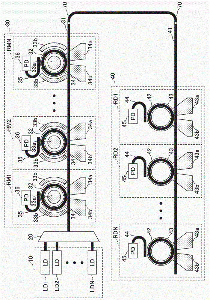
[0034] First, based on figure 1 A wavelength division multiplexing communication device including an optical element that is a controlled object in the optical element control method in the first embodiment will be described. The wavelength division multiplexing communication device includes a light source group 10 , a WDM multiplexer 20 , a ring modulator group 30 and a ring demultiplexer group 40 .

[0035] The light source group 10 includes a plurality of laser diodes as light sources emitting laser light waves (hereinafter referred to as "laser") having different wavelengths from each other, and the ring modulator group 30 includes a plurality of ring modulators having resonance wavelengths different from each other. . The ring demultiplexer group 40 includes a plurality of ring demultiplexers having resonance wavelengths different from each other. Furthermore, an optical fiber 70 is provided between the ring modulator group 30 and the ring demultiplexer group 40 . Inst...

no. 2 approach

[0068] Next, a second embodiment will be described. The present embodiment is a control method for an optical element having a structure in which the ring diameters of the ring resonators 32 of the ring modulators RM1, RM2, . . . 10 does not sequentially become larger or smaller as it goes downstream. That is, if Figure 9 As shown, the control method is a control method for the ring modulators RM1, RM2, . ,..., RM8. In this case, if Figure 10 As shown, the resulting PPM has rows of elements that do not necessarily decrease monotonically as one goes to the right, and whitespace is positioned irregularly. Therefore, blank-free diagonal sequences do not necessarily exist. In such cases, the columns are swapped into a different ordering such that the elements in the same row decrease monotonically as they go to the right, to obtain such as Figure 11 The PPM shown causes the order of the columns to be changed. After that, by applying the same processing as that in the fir...

no. 3 approach

[0070] Next, a third embodiment will be described. In the first and second embodiments described above, the laser diodes can have corresponding ring modulators assigned, and the resonance wavelength of the ring resonators of the ring modulators can be adjusted. However, the resonance wavelength of the ring resonator and the wavelength of the laser light emitted from the laser diode vary depending on the ambient temperature, and fine tuning is always required. The present embodiment handles such temperature changes.

[0071] Specifically, such as Figure 12 As shown, initial wavelength adjustment is first performed by setting the electric power supplied to the heater 34 in the ring modulator based on PPM at step S102.

[0072] Then, in step S104, feedback control is performed so that the light intensity detected at the photodetector 36 of the ring modulator takes a certain value to keep the wavelength relationship with the laser diode suitable for modulation.

[0073] At thi...


PUM


Abstract

A control method of an optical element, including light sources to emit lights having different wavelengths from each other, and ring modulators connected in cascade along a light waveguide, is disclosed. Each ring modulator includes a ring resonator, and a wavelength adjustment electrode to adjust a resonance wavelength in the ring resonator, wherein the lights from the light sources are multiplexed to enter the light waveguide. The method includes having a light source emit the light; adjusting power to the wavelength adjustment electrode in each ring modulator, to obtain a value of the power causing the resonance wavelength of the ring resonator, equivalent to the wavelength of the light emitted from the light source; obtaining a relationship between the light sources and the values of the power corresponding to the ring modulators; and selecting the ring modulators corresponding to the light sources based on the relationship.

Description

technical field [0001] The disclosure herein relates generally to methods of controlling optical elements. Background technique [0002] As one of optical communication technologies, there already exists a large-capacity optical fiber communication system using wavelength division multiplexing (WDM) technology. In such a large-capacity optical fiber communication system using wavelength division multiplexing (WDM) technology, an optical signal formed by a plurality of light sources having different wavelengths is transmitted in an optical fiber as a WDM signal, which makes high-capacity communication possible. That is, WDM signals are transmitted such that signals having mutually different wavelengths are respectively transmitted as signal components of independent channels, and thus, large-capacity communication is realized. A wavelength division multiplexing communication device using such a wavelength division multiplexing technique includes a demultiplexer that separate...

Claims


Application Information

Patent Timeline
IPC IPC(8): G02F1/025
CPCG02B6/2938G02F1/225G02B6/12007G02F1/0121G02B6/29338G02F1/0147G02F1/025G02F2203/05G02F2203/15G02B6/29391G02B6/29395H04J14/0221
Inventor 秋山知之
Owner FUJITSU LTD
Why Eureka
Try Eureka