
Oscillator

A technology of oscillators and inverters, applied in the direction of pulse generation, electrical components, and electric pulse generation

Inactive Publication Date: 2015-09-23
ULTRA CHIP INC
View PDF7 Cites 5 Cited by
  • Summary
  • Abstract
  • Description
  • Claims
  • Application Information

AI Technical Summary

Problems solved by technology

[0003] The technical problem solved by the present invention is to provide an oscillator to solve or improve the above problems

Method used

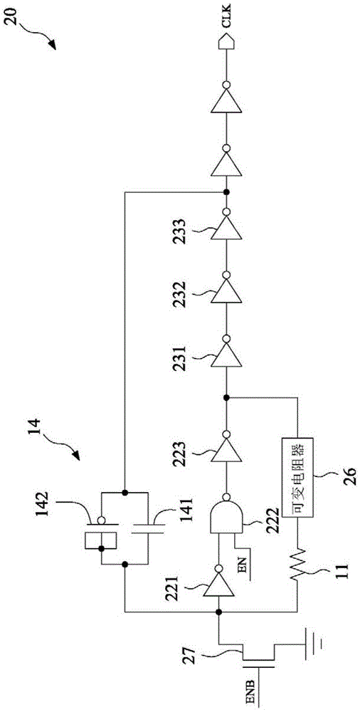
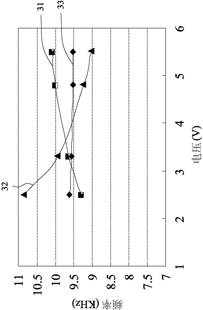

Image

  • Oscillator
  • Oscillator
  • Oscillator

Examples


Embodiment Construction

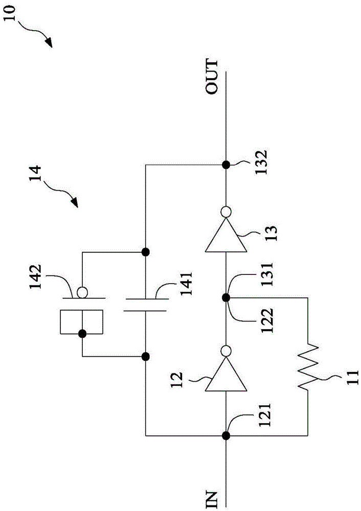
[0027] figure 1 A schematic circuit diagram of an embodiment of an oscillator of the present invention is shown. The oscillator 10 of the present invention includes: a resistor 11 , at least one first inverter 12 , at least one second inverter 13 and a capacitor bank 14 . In one embodiment, the oscillator 10 is an RC oscillator, which can be applied to low frequency signals, such as 1K Hz to 10MHz. The first inverter 12 is connected in parallel with the resistor 11 , and the first inverter 12 has an input terminal 121 and an output terminal 122 . The second inverter 13 has an input end 131 and an output end 132 , the input end 131 of the second inverter 13 is connected to the output end 122 of the first inverter 12 .

[0028] The capacitor bank 14 is connected to the input terminal 121 of the at least one first inverter 12 and the output terminal 132 of the at least one second inverter 13, and the capacitor bank 14 includes a first capacitor 141 and a first capacitor 141. T...


PUM


Abstract

The invention provides an oscillator, including a resistor, at least one first reverser, at least one second reverser and a capacitor bank. The at least one first reverser is connected with the resistor in parallel, and has an input end and an output end. The at least one second reverser has an input end and an output end, the input end of the at least one second reverser is connected to the output end of the at least one first reverser. The capacitor bank is connected with the input end of the at least one reverser and the output end of the at least one second reverser, and includes a first capacitor and a second capacitor, the first capacitor has a negative voltage coefficient, and the second capacitor has a positive voltage coefficient. By utilization of mutual compensation of the first capacitor and the second capacitor, the oscillator can be free of influence of voltage variation, so as to maintain stable output frequency.

Description

technical field [0001] The present invention relates to an oscillator. Background technique [0002] Oscillators are electronic circuits used to generate periodic signals, which can be sine waves, square waves, or triangle waves. The RC oscillator is a type of oscillator, which utilizes the charging, discharging and coupling of a resistor (R) and a capacitor (C) to output a periodic signal. Generally speaking, RC oscillators are more sensitive to changes in the manufacturing process of components, temperature or voltage, etc., and are greatly affected by the above changes. Contents of the invention [0003] The technical problem solved by the present invention is to provide an oscillator to solve or improve the above problems. [0004] The technical solution for solving the problem of the present invention is to provide an oscillator, including: a resistor, at least one first inverter, at least one second inverter and a capacitor bank. The at least one first inverter is...

Claims


Application Information

Patent Timeline
IPC IPC(8): H03K3/011
Inventor 张正欣陈建廷叶佳楠
Owner ULTRA CHIP INC
Learn More