Boosting dual-filter type gate driving system for blue light-emitting diode (LED) lamp

An LED lamp and gate drive technology, applied in the direction of light source, electric light source, electric lamp circuit layout, etc., can solve the problems of shortening startup time, high current noise, long startup time, etc., to improve accuracy and stability, reduce current Noise, good filtering effect

Inactive Publication Date: 2015-09-23
CHENGDU LEIKEER SCI & TECH
View PDF0 Cites 2 Cited by
  • Summary
  • Abstract
  • Description
  • Claims
  • Application Information

AI Technical Summary

Problems solved by technology

[0003] The purpose of the present invention is to overcome the defects of high energy consumption, large current noise and long start-up time in the current gate drive circuit, and provide a reasonable structure design, which can effectively reduce power consumption and current noise, and significantly shorten the start-up time The boost double-filter blue LED lamp grid drive system

Method used


Image

  • Boosting dual-filter type gate driving system for blue light-emitting diode (LED) lamp
  • Boosting dual-filter type gate driving system for blue light-emitting diode (LED) lamp

Examples


Embodiment

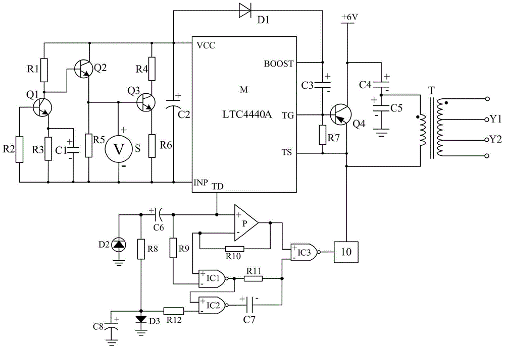
[0020] Such as figure 1 As shown, the present invention consists of a transistor Q4, a transformer T, a driver chip M, a switching current source, a diode D1, a capacitor C3, a resistor R7, a capacitor C4, and a capacitor C5, a boost double filter circuit 10, and a beam-excited logic amplifier circuit. . When connecting, the switching current source needs to be connected in series between the VCC pin and the INP pin of the driver chip M, and the diode D1 is connected in series between the VCC pin and the BOOST pin of the driver chip M, and the capacitor C3 is connected in series to the driver chip M. Between the BOOST pin and the TG pin of the chip M, and the resistor R7 is connected in series between the TG pin and the TS pin of the driving chip M.

[0021] The base of the transistor Q4 is connected to the TG pin of the driving chip M, its collector is grounded after passing through the capacitor C4 and capacitor C5 in sequence, and its emitter is grounded. At the same time...


PUM


Abstract

The invention discloses a novel gate drive system for blue LED lamps. The novel gate drive system mainly comprises a transformer T, a driver chip M, a switching current source, a diode D1, a capacitor C3, a resistor R7 and a transistor Q4, wherein the switching current source is serially connected between a VCC pin and an INP pin of the driver chip M, the diode D1 is serially connected between the VCC pin and a BOOST pin of the driver chip M, the capacitor C3 is serially connected between the BOOST pin and a TG pin of the driver chip M, the resistor R7 is serially connected between the TG pin and a TS pin of the driver chip M, a base electrode of the transistor Q4 is connected with the TG pin of the driver chip M, a collecting electrode of the transistor Q4 is grounded after passing by a capacitor C4 and a capacitor C5 sequentially, and an emitting electrode of the transistor Q4 is grounded. The novel gate drive system for the blue LED lamps has the functions of short-circuit protection, overvoltage protection and open-circuit protection and is low in power consumption, and starting time of the novel gate drive system is one fourth of that of a traditional gate drive circuit.

Description

technical field [0001] The invention relates to an LED driving circuit, in particular to a grid driving system for boosting double-filtering blue LED lamps. Background technique [0002] At present, due to the characteristics of low energy consumption, long service life, safety and environmental protection, LED lamps have become one of the mainstream products for people's living lighting. Since the LED lamp is different from the traditional incandescent lamp, it needs to be driven by a dedicated driving circuit. However, due to the unreasonable design structure of the currently widely used gate drive circuit, the current gate drive circuit has defects such as high energy consumption, large current noise, and long start-up time. Contents of the invention [0003] The purpose of the present invention is to overcome the defects of high energy consumption, large current noise and long start-up time in the current gate drive circuit, and provide a reasonable structure design, ...

Claims


Application Information

Patent Timeline
Patent Type & Authority Applications(China)
IPC IPC(8): H05B37/02H02M1/14
Inventor 黄涛
Owner CHENGDU LEIKEER SCI & TECH
Why Eureka
Try Eureka