Barrier composite for plastic components

A technology of plastic parts and composites, applied in the direction of battery pack parts, applications, electrical components, etc., to reduce production costs and improve mechanical properties

Active Publication Date: 2015-09-23
ROBERT BOSCH GMBH
View PDF8 Cites 4 Cited by
  • Summary
  • Abstract
  • Description
  • Claims
  • Application Information

AI Technical Summary

Problems solved by technology

There are currently no solutions on the market that allow structural components to maintain good barrier properties over extended periods of time

Method used


Image

  • Barrier composite for plastic components

Examples


Embodiment Construction

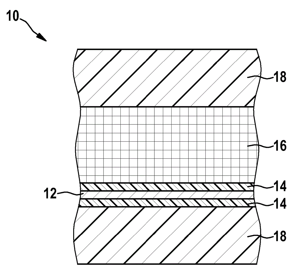
[0045] figure 1 A cross-section of the layered structure of the barrier composite 10 is schematically shown. The barrier composite 10 comprises a metal foil 12 , in particular an aluminum foil, with a thickness of, for example, 15 μm. The metal foil 12 functions as a barrier foil of the barrier composite 10 . Metal foil 12 has a coating 14 of thermoplastic, in particular polypropylene or polyamide 6 or polyamide 66, each having a thickness of, for example, 15 μm on both sides. The coated metal foil 12 forms a composite on one side with a fiber composite layer 16 comprising a thermoplastic matrix. The fiber composite layer 16 can be an impregnated and reinforced textile semi-finished product, a so-called organic board, having a thermoplastic as matrix material. The fabric semi-finished product may have a thickness of 1 mm. In particular, the organic sheet can have a glass fiber fabric with polypropylene or polyamide 6 or polyamide 66 as a matrix. The fiber composite layer ...


PUM

PropertyMeasurementUnit
thicknessaaaaaaaaaa
thicknessaaaaaaaaaa
thicknessaaaaaaaaaa

Abstract

The present invention relates to a barrier composite (10) for reducing the permeability of plastic components. The barrier composite comprises a metal foil (12), which has a coating on both sides made of a thermoplastic material (14), wherein a composite with a fibre composite layer (16) comprising a thermoplastic matrix is disposed on at least one side of the coated metal foil. The present invention further relates to a method for producing a component, in particular an encasement or a housing, made of such a barrier composite, and to the use thereof for encasing the plastic components.

Description

technical field [0001] The invention relates to a barrier compound for reducing the permeability of plastic parts, a method for producing a housing made of such a barrier compound and the use of such a barrier compound for For enclosing (Einhausung) plastic parts. Background technique [0002] If higher requirements are placed on the barrier properties of the components or packaging, these are usually made of metal, since plastics are not suitable for the production of these components due to their relatively high permeability. [0003] Insufficient barrier properties of plastics can in principle be improved in different ways. On the one hand, plastics can be modified, for example by increasing crystallization, adding additives or by replacing them with other plastic types or using so-called plastic blends. However, the permeability of the plastic can only be changed slightly by such a change in material. [0004] On the other hand, the barrier properties of plastic parts...

Claims


Application Information

Patent Timeline
Patent Type & Authority Applications(China)
IPC IPC(8): B29C70/08B32B15/08F17C1/04H01M2/02
CPCB32B27/32B32B27/286B32B2307/7242B32B5/024B32B27/40B32B2262/106B32B2262/0269B32B15/20B32B27/34B32B2255/06B32B15/08B29C70/088B32B15/14H01M2/0287B32B27/12B32B2255/26B32B2262/101B32B2457/10H01M50/124Y02E60/10
Inventor V.福格尔J.阿克曼
Owner ROBERT BOSCH GMBH
Why Eureka
Try Eureka