Variable geometry turbocharger

A technology of exhaust turbine and supercharger, which is applied in the direction of non-variable pumps, mechanical equipment, engine components, etc., which can solve the problems of turbine performance degradation and achieve the effect of simple structure

Inactive Publication Date: 2015-09-23
MITSUBISHI HEAVY IND LTD
View PDF4 Cites 8 Cited by
  • Summary
  • Abstract
  • Description
  • Claims
  • Application Information

AI Technical Summary

Problems solved by technology

In addition, if the clearance of the sliding part is enlarged t...

Method used


Image

  • Variable geometry turbocharger
  • Variable geometry turbocharger
  • Variable geometry turbocharger

Examples


Embodiment approach

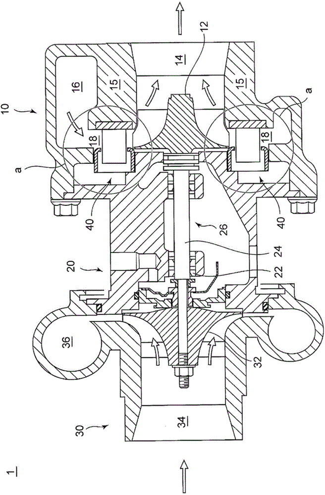
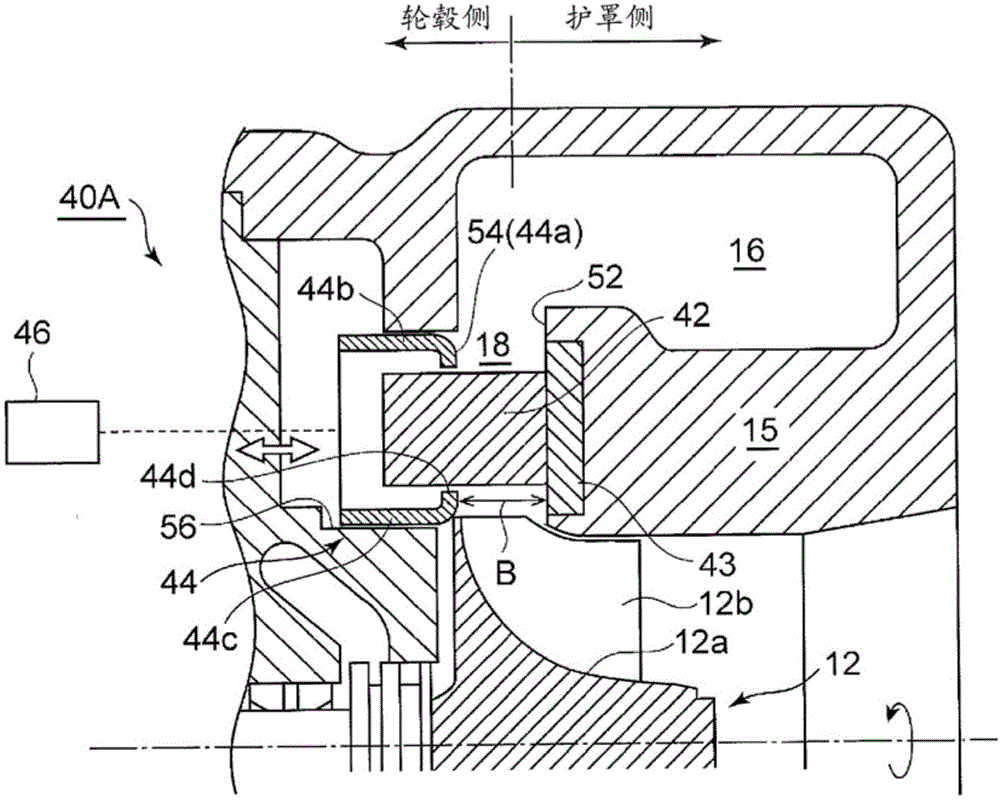
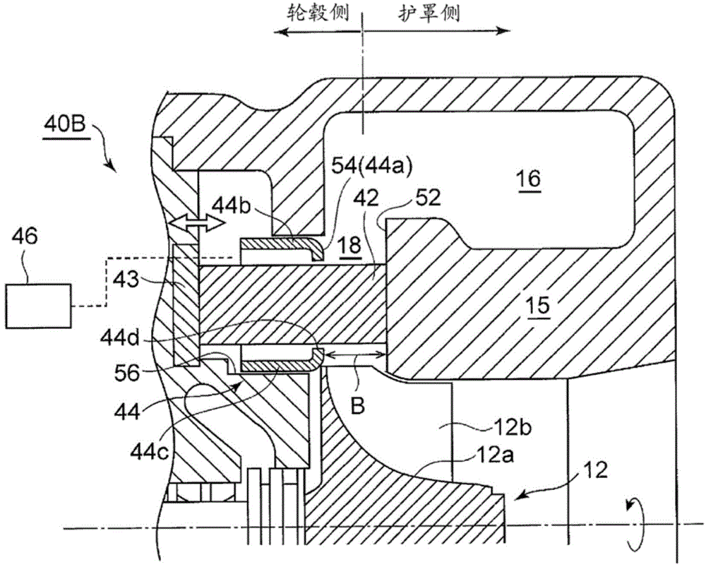
[0091] According to such an embodiment, since the cooling medium can be introduced from the cooling medium introducing mechanism 70 into the internal space 44f of the nozzle wall 44, the nozzle wall 44 can be effectively cooled. Furthermore, since the nozzle wall 44 has a rib portion 44e protruding from the peripheral end portion of the opening portion 44d toward the hub side, the cooling medium introduced into the internal space 44f is less likely to leak to the nozzle portion 18, and the turbine efficiency due to leakage of the cooling medium is prevented. decrease.

[0092] In addition, by forming the through hole 64 inside the nozzle vane 42 Figure 7 In the combination of the illustrated embodiments, the cooling medium introduced into the internal space 44 f flows through the through-holes 64 inside the nozzle vane 42 , so that the nozzle vane 42 can also be cooled simultaneously with the nozzle wall 44 .

[0093] Figure 9 It is a figure which shows the coolant introdu...


PUM


Abstract

[Problem] To provide a variable geometry turbocharger provided with a variable displacement mechanism in which the sliding part has a structure simplified compared with conventional ones. [Solution] This variable geometry turbocharger is provided with a turbine rotor (26) which comprises a rotation shaft (24) and a turbine wheel (12), a bearing housing (20) which houses a bearing device (22), a turbine housing (10) which rotatably houses the turbine wheel and in which an annular exhaust scroll unit (16) is formed through which exhaust gas flows, and a variable displacement mechanism (40) which is arranged inside of an annular nozzle unit (18) which guides into the turbine wheel the exhaust gas flowing through the exhaust scroll unit, wherein the variable displacement mechanism (40) includes a nozzle vane (42) which protrudes in an unrotatable state from the shroud side and/or the hub side of the nozzle unit towards the nozzle unit, an annular nozzle wall (44) which is configured so as to retract and advance freely from the hub side of the nozzle unit towards the shroud side, or from the shroud side towards the hub side and which can change the nozzle width B of the nozzle unit along the entire circumference, and a drive means (46) which advances and retracts the nozzle wall.

Description

technical field [0001] The present disclosure relates to a variable capacity exhaust gas turbocharger. Background technique [0002] The exhaust turbocharger often uses a variable capacity mechanism, which is arranged in the nozzle part between the annular exhaust scroll part formed in the turbine casing and the turbine impeller rotatably arranged in the center part of the turbine casing, and controls The flow of exhaust gas acting on the turbine wheel. [0003] As examples of this variable capacity mechanism, there are methods called a swing vane type and a sliding vane type. The swing vane type controls the flow of exhaust gas by rotating a movable vane arranged The nozzle wall of the nozzle vane advances and retreats toward the nozzle portion to control the flow of the exhaust gas. [0004] For example, Patent Document 1 discloses an example of a sliding vane type variable capacity exhaust turbocharger. [0005] prior art literature [0006] patent documents [0007]...

Claims


Application Information

Patent Timeline
IPC IPC(8): F02B37/24F02B39/00
CPCF02B39/005F02B37/22F05D2220/40F01D17/143Y02T10/144F01D5/18F01D17/16F02B37/168F02B37/24Y02T10/12F04D27/002
Inventor 茨木诚一铃木浩横山隆雄
Owner MITSUBISHI HEAVY IND LTD
Why Eureka
Try Eureka