Supercharge Your Innovation With Domain-Expert AI Agents!

Upwards-floating type oil-water separator

A technology of oil-water separator and separation container, applied in liquid separation, separation method, chemical instrument and method, etc., can solve the problems of insufficient utilization rate of cutting fluid, low working efficiency of belt-type oil-water separator, incomplete separation, etc. , to save space, reduce the number of water tank maintenance, and not easy to deteriorate.

Inactive Publication Date: 2015-09-30
NINGXIA KOCEL MACHINE TOOL ACCESSORIES
View PDF10 Cites 4 Cited by
  • Summary
  • Abstract
  • Description
  • Claims
  • Application Information

AI Technical Summary

Problems solved by technology

At present, most domestic devices for effectively separating cutting fluid and oil rely on belt-type oil-water separators, but the working efficiency of belt-type oil-water separators is low, the separation is not complete, and the utilization rate of cutting fluid does not meet people's expectations.

Method used


Image

  • Upwards-floating type oil-water separator
  • Upwards-floating type oil-water separator

Examples


Embodiment Construction

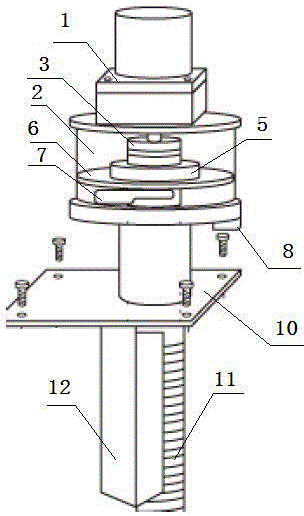
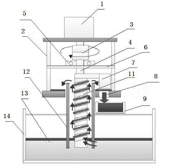
[0015] Such as figure 1 , 2 As shown, a floating oil-water separator according to the present invention includes a motor 1, a separation container 2, a coupling 3, a partition 6, a sealing plate 5, a rotating shaft 4, an oil scraper 7, a screw rod 11, a retaining Oil plate 12, connection plate 10, oil receiving box 9.

[0016] The motor 1 is fixed on the upper surface of the separation container 2, electrically connected to the coupling 3; the partition plate 6 is located inside the separation container 2, and the separation container 2 is divided into upper and lower layers. There is a circular through hole, the rotating shaft 4 passes through the circular through hole of the partition 6 and is connected with the screw rod 11, the sealing plate 5 is located on the partition 6, and is nested and installed on the rotating shaft 4 to prevent floating The oil splashes to the upper layer of the separation container 2 through the gap between the circular through hole of the parti...


PUM


Abstract

An upwards-floating type oil-water separator comprises a motor, a separation container, a coupler, a partition, a seal plate, a rotating shaft, an oil scraping plate, a spiral rod, oil baffle plates, a connecting plate and an oil receiving box, wherein the motor is fixed on the upper surface of the separation container, and is electrically connected with the coupler; the partition is positioned in the separation container to divide the separation container into an upper layer and a lower layer. The upwards-floating type oil-water separator with the technical scheme has the benefits as follows: the separating efficiency is improved, cutting fluid and floating oil can be separated relatively radically, the frequency for maintenance of a water tank is reduced, and the machine tool operation efficiency is improved; the separation efficiency of the cutting fluid and floating oil is improved, the cutting fluid is not easy to deteriorate, the amount of generated waste liquid is reduced, and the production operation cost is reduced; moreover, the oil-water separator is small in size, so that the occupied space is reduced.

Description

technical field [0001] The invention relates to the field of separation of cutting fluid and floating oil in the machine tool industry, in particular to a floating oil-water separator. Background technique [0002] In the field of machine tool industry, a large amount of slick oil will enter the cutting fluid during the operation of the machine tool and form a mixture with the cutting fluid. If the slick oil and cutting fluid are mixed together for a long time, the cutting fluid will deteriorate and cannot be used, seriously affecting the work of the machine tool. efficiency and operating costs. Therefore, in order to save costs, manufacturers generally separate the cutting fluid from floating oil to realize the reuse of cutting fluid. At present, most domestic devices for effectively separating cutting fluid and oil rely on belt-type oil-water separators, but belt-type oil-water separators have low working efficiency and incomplete separation, and the utilization rate of c...

Claims


Application Information

Patent Timeline
IPC IPC(8): B01D17/022B01D17/035C10M175/00
Inventor 赵龙王虎何国锋马同堂孙冠琳
Owner NINGXIA KOCEL MACHINE TOOL ACCESSORIES
Features
  • R&D
  • Intellectual Property
  • Life Sciences
  • Materials
  • Tech Scout
  • Unparalleled Data Quality
  • Higher Quality Content
  • 60% Fewer Hallucinations
Learn More