Punching die for door and window glass guide groove

A technology of door and window glass and punching molds, which is applied in the field of mechanical processing, can solve problems such as difficult guarantees, numerous processes, and unguaranteed processing quality, so as to improve product quality and rhythm, reduce manual work time, and eliminate the occurrence of defective products. Effect

Active Publication Date: 2015-09-30
GUANGZHOU MINTH AUTOMOBILE PARTS CO LTD
View PDF6 Cites 3 Cited by
  • Summary
  • Abstract
  • Description
  • Claims
  • Application Information

AI Technical Summary

Problems solved by technology

In the prior art, 4 pairs of molds are used, 2 people correspond to 5 stations, and the production is divided into multiple times. There are many processes, and one-time positioning cannot be realized. There will be the following problems in the punching process: the position of the holes will be deviated during multiple processing, resulting in difficulty in assembly. Abnormal sound is generated, and it is even difficult to install the car; the material of the door glass run channel itself is thin, and the cutting length of the front side is long and the rigidity is poor. It is difficult to ensure the angle in both directions after multiple processing, resulting in deformation and even cracking of the door glass run channel
The processing quality cannot be guaranteed, there are many equipment and personnel, and the production efficiency is low

Method used


Image

  • Punching die for door and window glass guide groove
  • Punching die for door and window glass guide groove
  • Punching die for door and window glass guide groove

Examples


Embodiment Construction

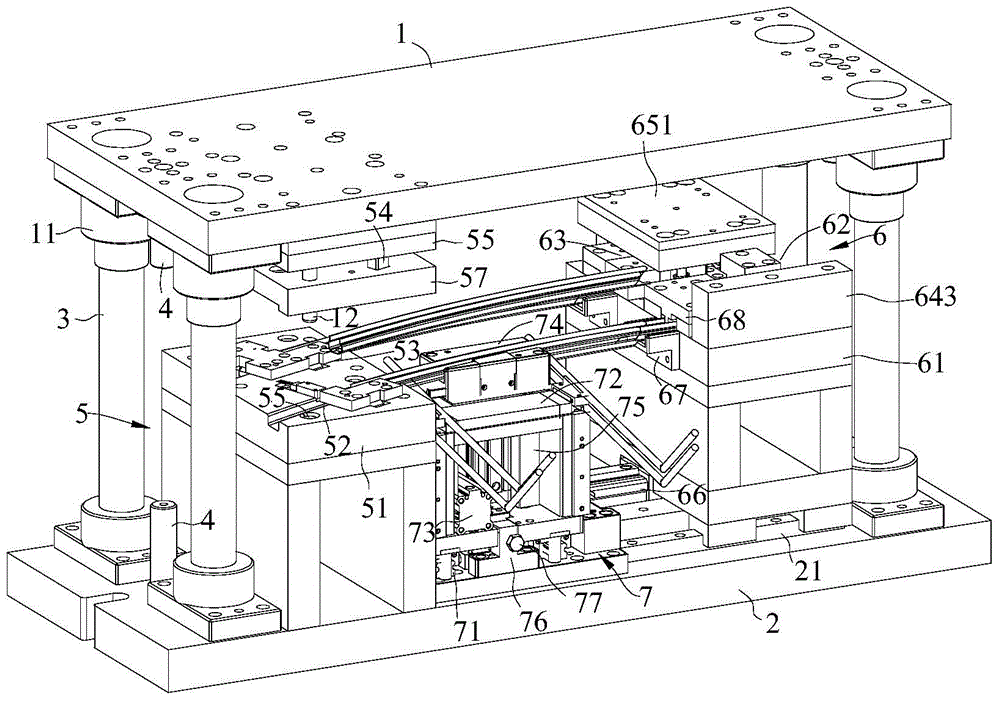
[0020] refer to figure 2 , which shows the specific structure of the preferred embodiment of the present invention. The structural characteristics of each element of the present invention will be described in detail below, and if there is a description of the direction (up, down, left, right, front and back), it is based on figure 2 The structure shown is a reference description, but the actual application direction of the present invention is not limited to this.

[0021] The present invention provides a punching die for a door and window glass run channel, comprising an upper template 1, a lower template 2 and a guide post 3, the guide post 3 is installed at the four corners of the lower template 2, and the upper template 1 is set on the On the guide post 3, a return spring is set between the guide sleeve 11 and the lower template 2 on the guide post 3, and the upper template 1 and the lower template 2 are equipped with a position-limiting post 4 extending oppositely. A ...


PUM


Abstract

The invention discloses a punching die for a door and window glass guide groove. The punching die comprises an upper die plate, a lower die plate, guide posts, a left side punching mechanism, a right side punching mechanism and a movable clamping claw; the left side punching mechanism comprises a left side punching base with a left side first punching position and a left side second punching position, a plunger chip is installed on the upper die plate, and the right side punching mechanism comprises a right side punching base with a right side first punching position, a right side second punching position, a right side first plunger chip mechanism and a right side second plunger chip mechanism; the left side first punching position and the right side first punching position form a first station, and the left side second punching position and the right side second punching position form a second station. Punching of the two stations is achieved on one die, the two stations share one oil press, the space occupancy rate is small, the punching die is convenient and fast to operate, manual operation time is shortened, the product quality is promoted, the tatk is accelerated, the product qualification precision is met, and defective products are eradicated.

Description

technical field [0001] The invention is used in the technical field of mechanical processing, and in particular relates to a punching die for glass run grooves of doors and windows. Background technique [0002] Such as figure 1 As shown, the door glass guide channel is a part assembled on the window frame of the car door to realize the function of guiding the car door. In the prior art, 4 pairs of molds are used, 2 people correspond to 5 stations, and the production is divided into multiple times. There are many processes, and one-time positioning cannot be realized. There will be the following problems in the punching process: the position of the holes will be deviated during multiple processing, resulting in difficulty in assembly. Abnormal noises are generated, and it is even difficult to install the car; the material of the door glass run channel itself is thin, the length of the front side is long and the rigidity is poor, and it is difficult to ensure the angle of th...

Claims


Application Information

Patent Timeline
Patent Type & Authority Applications(China)
IPC IPC(8): B21D28/14B21D37/12
CPCB21D28/14B21D37/12
Inventor 夏贤懿
Owner GUANGZHOU MINTH AUTOMOBILE PARTS CO LTD
Why Eureka
Try Eureka