Technology for manufacturing mounted bearing pedestal and numerical control special machine tool thereof

A technology of bearings with seats and special machine tools, which is applied in the direction of manufacturing tools, other manufacturing equipment/tools, metal processing machinery parts, etc., can solve serious processing quality problems, serious quality problems, etc., achieve accuracy and quality level improvement, and reduce operating noise The effect of reducing and eliminating the shape error of the inner spherical surface

Active Publication Date: 2015-09-30
庄有土
View PDF7 Cites 9 Cited by
  • Summary
  • Abstract
  • Description
  • Claims
  • Application Information

AI Technical Summary

Problems solved by technology

[0008] The purpose of the present invention is to provide a process for manufacturing the bearing seat of the bearing with seat, so as to solve the serious quality problem caused by the inner spherical surface processing of the bearing seat caused by the two cast bearing insertion grooves in the prior art
[0009] Another object of the present invention is to provide a numerically controlled machine tool for manufacturing the bearing seat of the bearing seat, so as to solve the serious quality problem caused by the two cast bearing insertion grooves in the prior art to the inner spherical surface processing of the bearing seat

Method used


Image

  • Technology for manufacturing mounted bearing pedestal and numerical control special machine tool thereof
  • Technology for manufacturing mounted bearing pedestal and numerical control special machine tool thereof
  • Technology for manufacturing mounted bearing pedestal and numerical control special machine tool thereof

Examples


Embodiment Construction

[0032] In order to further explain the technical solution of the present invention, the present invention will be described in detail below through specific examples.

[0033] A process for manufacturing a bearing seat of a bearing with seat according to the present invention is mainly realized through the following steps:

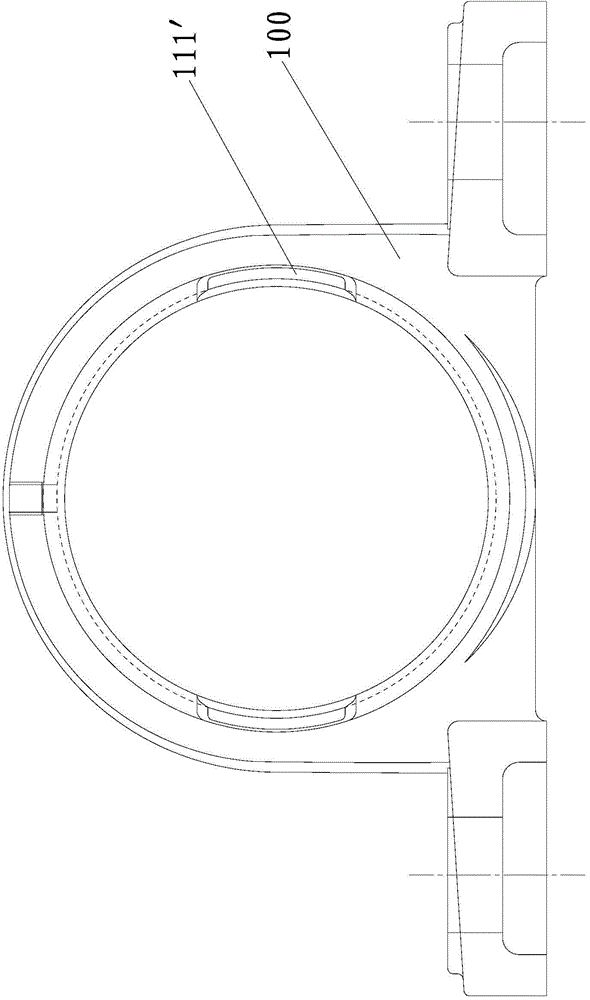
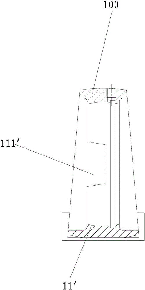
[0034] 1. Cast the bearing seat blank with inner hole but no bearing insertion groove, anneal, grind the parting surface flash, and mill the installation datum surface;

[0035] 2. Perform CNC rough turning, semi-finish turning and turning oil groove on the inner spherical surface of the bearing seat blank in step 1;

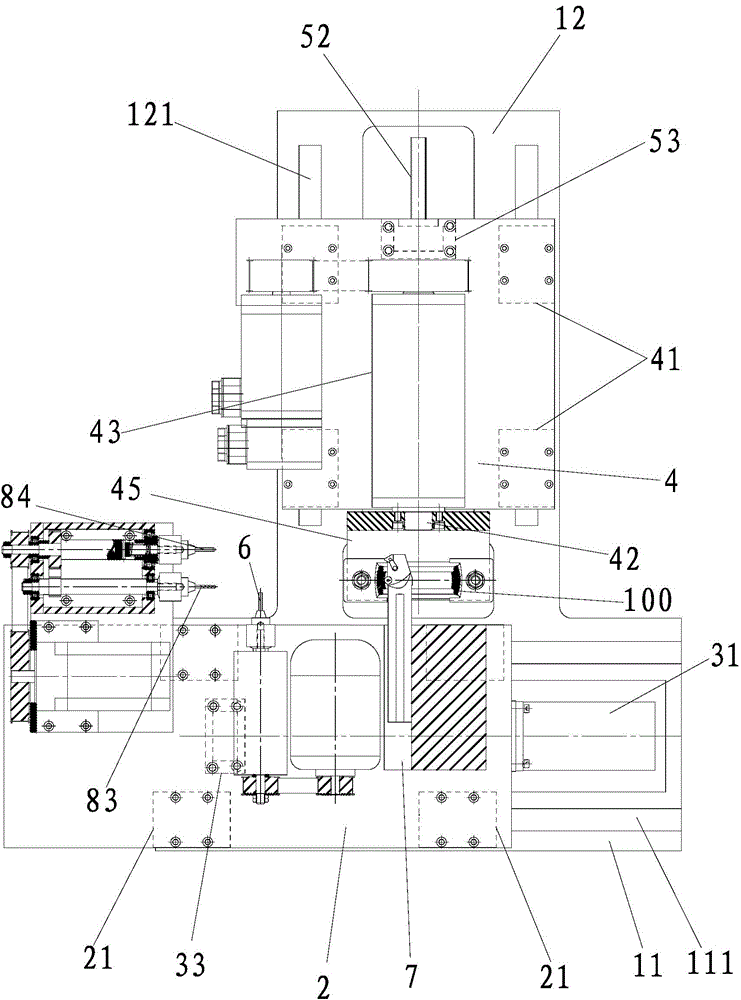
[0036] 3. Carry out CNC finish turning on the inner spherical surface of the bearing seat blank in step 2 to obtain a preprocessed part, that is, use a CNC special machine tool to perform finish turning on the inner spherical surface of the bearing seat blank after semi-finishing turning;

[0037] 4. Use an end mill to mill two oppositely s...


PUM


Abstract

The invention discloses a technology for manufacturing a mounted bearing pedestal. The method comprises the main following steps that 1, a bearing pedestal workblank with an inner hole and no bearing insertion slot is cast, and an installation reference plane of the bearing workblank is milled; 2, rough turning and half finish turning are performed on the inner spherical surface of the bearing pedestal workblank, and an oil groove is turned; 3, finish turning is performed on the inner spherical surface of the bearing pedestal; 4, two opposite bearing insertion slots are milled through an end mill; 5, an oil injection hole is drilled; 6, oil injection hole threads are tapped, and finally the bearing pedestal is obtained. The technology that finish machining is performed on the inner spherical face and then the bearing insertion slots are milled is the core of the technology for manufacturing the mounted bearing pedestal. The technology has the advantages that no bearing insertion slot exists when the inner spherical face of the bearing pedestal is turned, so that the serious manufacturing quality problem caused when bearing insertion slots exist in the steps of rough turning, half finish turning and finish turning of the inner spherical face of the bearing pedestal is avoided, and the precision and surface quality grade of the bearing pedestal are remarkably improved. In order to improve production efficiency, the invention further discloses a numerical control special machine tool for manufacturing the mounted bearing pedestal.

Description

technical field [0001] The invention relates to a bearing seat of a bearing with a seat, in particular to a process for manufacturing a bearing seat of a bearing with a seat and a special numerical control machine tool thereof. Background technique [0002] The outer spherical ball bearing with seat, referred to as the bearing with seat, is a bearing unit that combines the bearing and the bearing seat; the outer surface of the outer ring of the bearing is spherical, and the bearing seat must have a spherical shape for the bearing to be installed inside. Bore. Bearings with housings are simple to manufacture, low in cost, easy to assemble and maintain, and are standard components with a wide range of uses. The bearing with seat has two kinematic pairs, one is a rotary kinematic pair that rotates around its axis, and the other is a spherical kinematic pair that allows its axis to swing. As a kinematic pair, the outer spherical surface roughness of the outer ring of the beari...

Claims


Application Information

Patent Timeline
Patent Type & Authority Applications(China)
IPC IPC(8): B23P15/00B23P23/02B23Q5/36B23Q5/40B23Q5/10B23Q5/14
CPCB23P15/003B23P23/02B23Q5/10B23Q5/147B23Q5/36B23Q5/40
Inventor 庄有土
Owner 庄有土
Why Eureka
Try Eureka