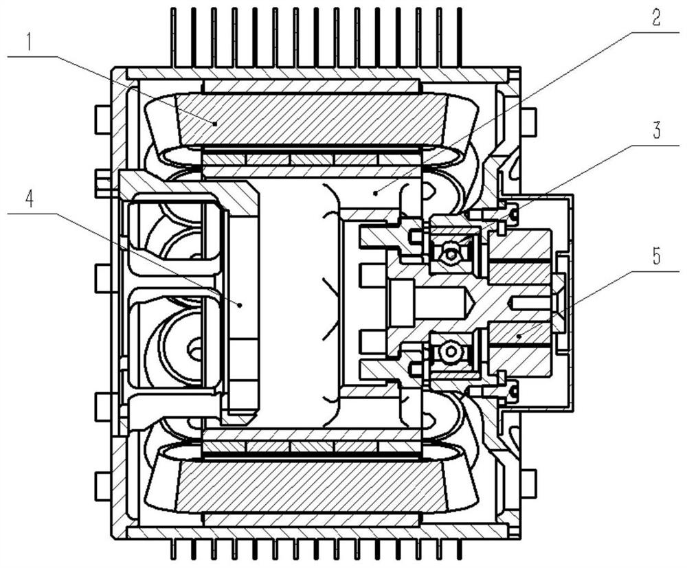
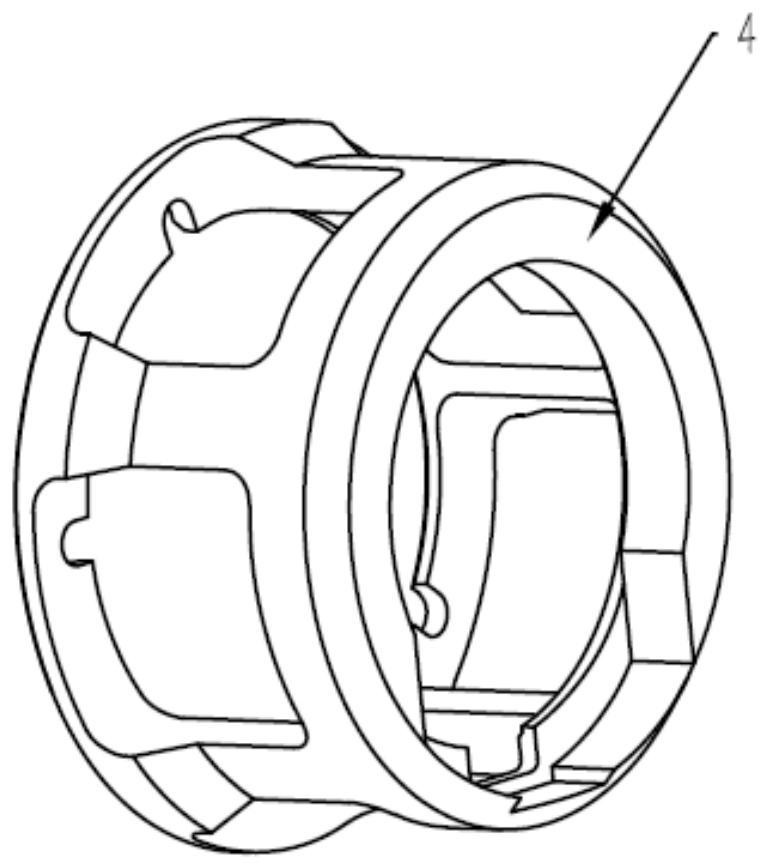
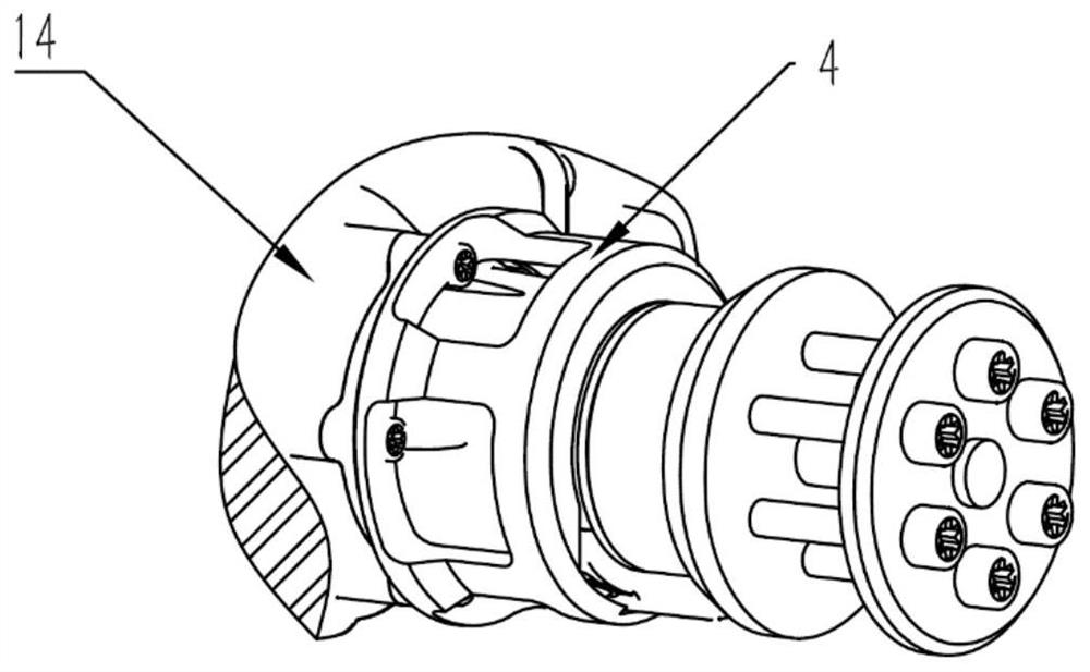
Direct drive type inner rotor starting generator system of aero-engine

A technology for starter generators and aero-engines, which is applied in the manufacture of motor generators, electromechanical devices, and stator/rotor bodies, etc., can solve the problems of inability to accurately detect the rotor position, inability to adapt to high power requirements, and low rectification efficiency. The connection structure is simple and reliable, the installation structure is simple and reliable, and the power generation efficiency is high.

Active Publication Date: 2021-11-05
BEIHANG UNIV
View PDF8 Cites 0 Cited by
  • Summary
  • Abstract
  • Description
  • Claims
  • Application Information

AI Technical Summary

Problems solved by technology

The structure of the cantilever beam limits the increase in the axial length of the starter generator, thereby limiting the increase in power, and is not suitable for the higher electric power demand of all-electric propulsion UAVs
In addition, the unmanned aerial vehicle that adopts the all-electric propulsion scheme realizes the decoupling of the engine and the propeller. The propeller is distributed in different positions of the fuselage. The engine and the starter generator are usually required to be installed in the belly, and the rotation of the outer rotor structure starter generator Parts are exposed, which poses a great safety hazard to other equipment in the belly, and is not suitable for all-electric propulsion drones
At the same time, the original structure is not equipped with a resolver, and the rotor position cannot be accurately detected. The AC power of the generator can only be converted into the DC power required by the aircraft by means of uncontrollable rectification. The rectification efficiency is low, and it cannot adapt to the high power of the new starter generator system. Require

Method used


Image

  • Direct drive type inner rotor starting generator system of aero-engine
  • Direct drive type inner rotor starting generator system of aero-engine
  • Direct drive type inner rotor starting generator system of aero-engine

Examples


Embodiment Construction

[0030] Various exemplary embodiments, features, and aspects of the invention will be described in detail below with reference to the accompanying drawings. The same reference numbers in the figures indicate functionally identical or similar elements. While various aspects of the embodiments are shown in drawings, the drawings are not necessarily drawn to scale unless specifically indicated.

[0031] The word "exemplary" is used exclusively herein to mean "serving as an example, embodiment, or illustration." Any embodiment described herein as "exemplary" is not necessarily to be construed as superior or better than other embodiments.

[0032] In addition, in order to better illustrate the present invention, numerous specific details are given in the specific embodiments below. It will be understood by those skilled in the art that the present invention may be practiced without certain of the specific details. In some instances, methods, means, components and circuits well kn...


PUM


Abstract

The invention relates to a direct drive type inner rotor starting generator system of an aero-engine and belongs to the field of unmanned aerial vehicle oil-electricity hybrid power. A starter generator outer stator assembly is fixedly installed on the aero-engine through a stator support, so that the starting generator system is compact in structure, short in axial length, high in integration level and high in power-to-weight ratio; coaxiality of a starting generator stator and the engine is guaranteed through supporting of the stator support, a starting generator inner rotor assembly is directly installed on an aero-engine shaft, the starting generator system does not need to be supported by a bearing on the side close to the engine, the starting generator system is supported by a single bearing on the side far away from the engine, bearing heating is reduced, and bearing reliability is improved; and a rotary transformer is arranged at the end, away from the aero-engine, of the rotating shaft of the starting generator inner rotor assembly, the position of a rotor can be accurately detected, and therefore the starting generator system can output high-power direct current in a controllable rectification mode, and the power generation efficiency is high.

Description

technical field [0001] The invention belongs to the technical field of starter generators for small and medium-sized unmanned aerial vehicles, and in particular relates to a single-bearing-supported direct-drive inner-rotor starter-generator system in which the output shafts of small and medium-sized aero-engines for drones are arranged in series, and in particular to an all-electric starter generator system. Piston-type aeroengine direct-drive inner rotor starter-generator system for propulsion of small and medium-sized UAVs. Background technique [0002] In the all-electric propulsion of small and medium-sized unmanned aerial vehicles, it is an important development trend to use a small aero-engine to drive a generator to generate electricity to form a DC power supply for the whole machine. The all-electric propulsion UAV platform puts forward requirements for the starter generator system with small size, high integration, high power, and high power-to-weight ratio. At the...

Claims


Application Information

Patent Timeline
Patent Type & Authority Applications(China)
IPC IPC(8): H02K7/18H02K7/00H02K11/225H02K15/00H02K15/03
CPCH02K7/1815H02K7/003H02K11/225H02K15/00H02K15/03
Inventor 钱浩郑楚良吴凡生王英勋
Owner BEIHANG UNIV
Why Eureka
Try Eureka