Coaxial multi-slip-sheet wave-ring rotor machine

A wave ring rotor and sliding vane technology, applied in the field of coaxial multi-sliding vane wave ring rotor machines

Inactive Publication Date: 2002-12-18
徐浩冠
View PDF4 Cites 0 Cited by
  • Summary
  • Abstract
  • Description
  • Claims
  • Application Information

AI Technical Summary

Problems solved by technology

However, in our trial production practice, we found that the original wave ring machine scheme still has many shortcomings. After repeated failures, modifications, and improvements, we finally formed the coaxial multi-slide wave ring rotor machine scheme introduced to you now.

Method used

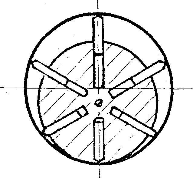
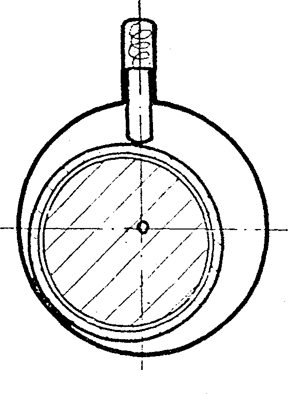
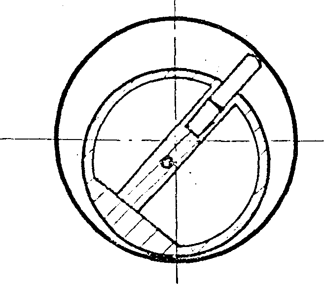

Image

  • Coaxial multi-slip-sheet wave-ring rotor machine
  • Coaxial multi-slip-sheet wave-ring rotor machine
  • Coaxial multi-slip-sheet wave-ring rotor machine

Examples


Embodiment approach

[0025] Below we recommend some of the most distinctive applications that can be successfully developed in the near future:

[0026] 1. Since this model can be designed to operate without internal compression process, the thickness of the sliding vane can be designed to be larger; the outer rotor can transmit larger torque, especially suitable for high-flow high-pressure oil pumps or hydraulic motors.

[0027] 2. The air intake of this model is concentrated in one place, and it is easy to develop into a high-speed and large-flow vacuum pump.

[0028] 3. In view of the characteristics of small size, large displacement, low vibration, low noise, and no need for pile foundation even for machines with large displacement, this model is most suitable for developing mobile air compressors for pneumatic tools in road and bridge trestle projects station, and other small multi-purpose mobile air compressors.

[0029] 4. For the same reason, we can also combine wave ring air compressors ...


PUM


Abstract

A piston machine able to generate variable volume directly by rotation is composed of annular wave rotor, cylindrical stator, three sets of slide pates arranged coaxially and convertged in space, andtwo end covers, and features that the rotor with cross-section of annular sine curve is matched with the slide plate sets of stator to realize new working mechanism. Its advantages include less friction loss, high volume efficiency and rotational speed, and low vibration and noise. It is suitable for compression, pumping and extraction of fluid.

Description

Technical field: [0001] The invention relates to a rotary piston variable volume machine in the field of machinery—a coaxial multi-slide wave ring rotor machine. It is essentially the improvement and development of the inventor's 92234322.5# Chinese patent, the wave ring type line sliding vane rotor machine (patent number 153179#, hereinafter referred to as the original wave ring machine). Successfully developed practical models. Background technique: [0002] The sliding vane rotor machine is one of the oldest rotary piston machines. It is very simple no matter from the structure of the whole machine or the manufacturing process. It's just that it has not been able to get rid of the problems of large friction loss, low mechanical efficiency, long sealing line, large leakage, and low volume utilization rate in the course of its development for more than 400 years. Therefore, it can only be used as a compressor or pump under low-medium pressure and low-medium speed, and ca...

Claims


Application Information

Patent Timeline
Patent Type & Authority Patents(China)
IPC IPC(8): F04C2/324F04C2/344
Inventor 徐侃峰徐浩冠
Owner 徐浩冠
Why Eureka
Try Eureka