

Computer-controlled expansion accumulative lifting method for erecting super-high arch grid structure
A grid structure and installation method technology, applied in the field of steel structures, can solve the problems of construction cost, construction quality, construction safety, no cases of completion acceptance, imperfections, etc., and achieve strong controllability of the construction period and low construction cost. low effect
- Summary
- Abstract
- Description
- Claims
- Application Information
AI Technical Summary
Problems solved by technology
Method used
Image


Examples
Embodiment 1
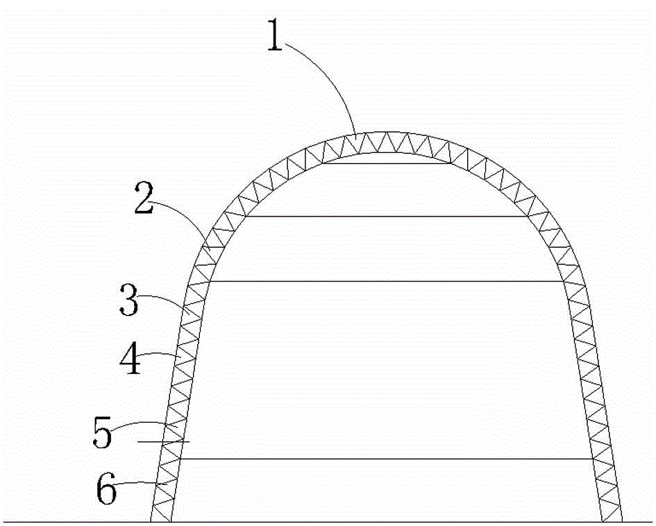
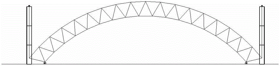
[0066] Embodiment 1: as figure 1 , figure 2 , image 3 , Figure 4 , Figure 5 , Figure 6 , Figure 7 , Figure 8 , Figure 9 , Figure 10 and Figure 11 As shown, the installation method of super-high arched grid structure computer-controlled external expansion cumulative lifting is carried out according to the following steps:
[0067] (1) Calculation and analysis before spinning:
[0068] Use calculation software to calculate and analyze the whole construction process to ensure that the structure itself and the lifting system can meet the relevant mechanical and structural requirements during the construction process, and ensure that the construction process is safe and controllable;
[0069] (4) Calculation control during construction:
[0070] The synchronous control requirements of hydraulic lifting construction are high, and the computer synchronous control system is adopted during the construction process, and the monitoring during the lifting process is s...
PUM
 Abstract
Description
Claims
Application Information