Phase change heat storage type solar energy evacuated collector tube and solar water heater comprising phase change heat storage type solar energy evacuated collector tube

A technology of vacuum heat collecting tubes and phase change heat storage, applied in solar heat collectors, solar heat collectors using working fluids, solar thermal energy, etc. Tube thermal expansion and other issues, to achieve the effect of increasing strength and pressure bearing capacity, reducing expansion and contraction resistance, and ensuring continuity

Active Publication Date: 2015-09-30
上海海大资产经营有限公司
View PDF10 Cites 13 Cited by
  • Summary
  • Abstract
  • Description
  • Claims
  • Application Information

AI Technical Summary

Problems solved by technology

But both have shortcomings. The former metal inner tube and glass outer tube are sealed by sealing materials, and there is no fusion sealing of glass and metal, which inevitably has problems of vacuum leakage and thermal expansion of the metal inner tube; while the latter increases the bellows structure, but because it is a straight-through type, both ends are sealed and fixed. Once the metal inner tube is heated and expanded, it must expand to one or both ends at the same time, so that the stretching force cannot be released and relieved.

Method used


Image

  • Phase change heat storage type solar energy evacuated collector tube and solar water heater comprising phase change heat storage type solar energy evacuated collector tube
  • Phase change heat storage type solar energy evacuated collector tube and solar water heater comprising phase change heat storage type solar energy evacuated collector tube

Examples


Embodiment Construction

[0021] The present invention will be further described below in conjunction with specific embodiments and accompanying drawings.

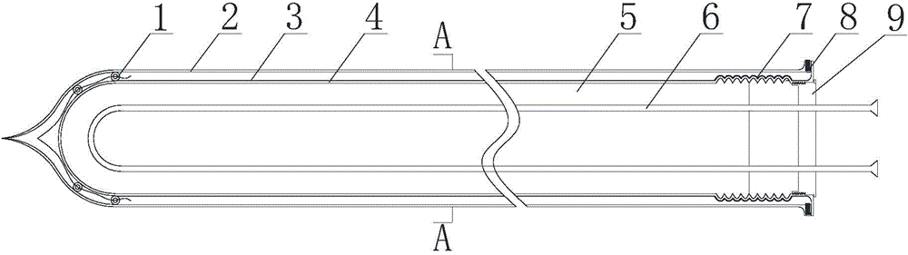
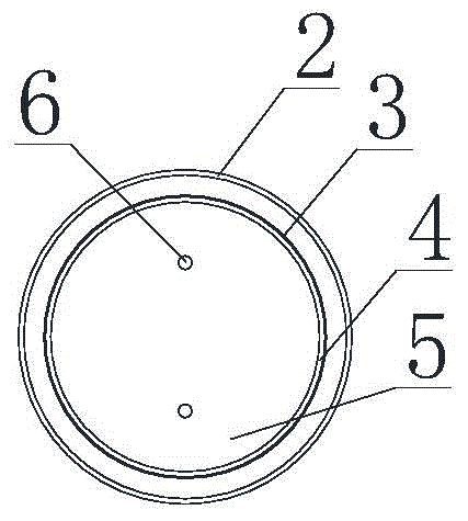
[0022] Such as figure 1 and figure 2 As shown, a phase change heat storage type solar vacuum heat collection tube includes an outer glass outer tube 2 and an inner metal inner tube 4 .

[0023] The metal inner tube 4 has a corrugated structure 7 close to its open end, the open end of the glass outer tube 2 and the open end of the metal inner tube 4 are welded through a Kovar ring 8, the closed end of the glass outer tube 2 and the metal inner tube An elastic sliding support 1 is arranged between the closed ends of 4 . After the opening end of the glass outer tube 2 and the opening end of the metal inner tube 4 are sealed, the closed end of the glass outer tube 2 is vacuumized so that the glass outer tube 2 and the metal inner tube 4 form a vacuum layer. Using the metal inner tube 4 with the corrugated structure 7 solves the problem that the inn...


PUM


Abstract

The invention relates to a phase change heat storage type solar energy evacuated collector tube and a solar water heater comprising the phase change heat storage type solar energy evacuated collector tube, which belong to the technical field of solar energy. The phase change heat storage type solar energy evacuated collector tube comprises a glass outer pipe of an outer layer and a metal inner pipe of an inner layer, a ripple structure is arranged on the metal inner pipe close to an opening end of the metal inner pipe, opening ends of the glass outer pipe and the metal inner pipe are welded through kovar alloy rings, elastic sliding support pieces are arranged between closed ends of the glass outer pipe and the metal inner pipe, vacuum parts are arranged between the glass outer pipe and the metal inner pipe, selective absorbing coatings are coated on pipe outer wall of the metal inner pipe, a sealing cover is arranged on the opening end of the metal inner pipe, phase change heat storage materials are filled in the metal inner pipe, a U-type heat exchange pipe is embedded in the phase change heat storage materials, and an inlet end and an outlet end of the U-type heat exchange pipe stretches outside the opening end of the metal inner pipe and pass through the sealing cover to fix. The phase change heat storage type solar energy evacuated collector tube and the solar water heater comprising the phase change heat storage type solar energy evacuated collector tube have the advantages of integrated heat collection and storage, no water tank, small space usage and large heat storage amount and the like.

Description

technical field [0001] The invention relates to a solar vacuum heat collecting tube, in particular to a phase change heat storage type solar vacuum heat collecting tube and a solar water heater composed of the same. Background technique [0002] Solar energy is a distributed and intermittent energy source. To make full use of it, energy storage technology is needed to store sufficient solar energy during the day for use at night or on cloudy days. Phase change heat storage technology is a very promising technology in the current energy storage technology. It has many advantages such as high energy storage density, constant temperature of charge and discharge, so it can be well applied to the heat storage and utilization of solar energy. However, a single phase-change heat storage material generally has the problems of large phase-change thermal expansion rate and low thermal conductivity, so it cannot be directly applied to existing all-glass vacuum heat collectors. [0003...

Claims


Application Information

Patent Timeline
Patent Type & Authority Applications(China)
IPC IPC(8): F24J2/24F24J2/34F24J2/46F24S10/70
CPCY02E10/44
Inventor 华维三章学来蒋春艳刘宇飞丁锦宏罗孝学
Owner 上海海大资产经营有限公司
Why Eureka
Try Eureka