Heat exchanger

A technology of heat exchangers and headers, applied in evaporators/condensers, lighting and heating equipment, refrigeration components, etc., can solve the problem of ineffective gas-liquid mixed heat exchange, low heat exchange performance of heat exchangers, etc. problems, to achieve the effect of avoiding redistribution, small wind resistance and good heat transfer performance

Active Publication Date: 2015-09-30
HANGZHOU SANHUA RES INST CO LTD
View PDF9 Cites 13 Cited by
  • Summary
  • Abstract
  • Description
  • Claims
  • Application Information

AI Technical Summary

Problems solved by technology

Due to the effect of viscous force, the liquid refrigerant will flow in the space close to the wall of the inner cavity of the flat tube, and when the gaseous refrigerant enters the flat tube, due to the influence of gravity and the resistance of the liquid refrigerant, it mainly passes through the center of the inner cavity of the flat tube, so that As a result, the flow channels of liquid refrigerant and gas refrigerant in the flat tube are separated from each other, and gas-liquid mixing and heat exchange cannot be performed effectively, resulting in low heat transfer performance of the heat exchanger

Method used


Image

  • Heat exchanger
  • Heat exchanger
  • Heat exchanger

Examples


Embodiment Construction

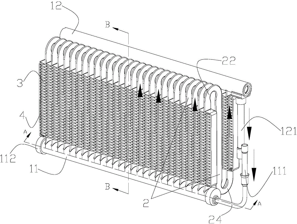
[0024] The invention provides a multi-layer micro-channel heat exchanger, wherein the flat tube includes at least two bending sections, which can avoid secondary distribution of refrigerant and avoid low heat transfer performance when gas-liquid mixing is uneven. question.

[0025] The heat exchanger of the present invention will be specifically described below in conjunction with the drawings and specific embodiments.

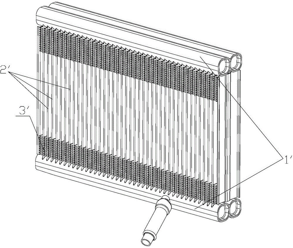
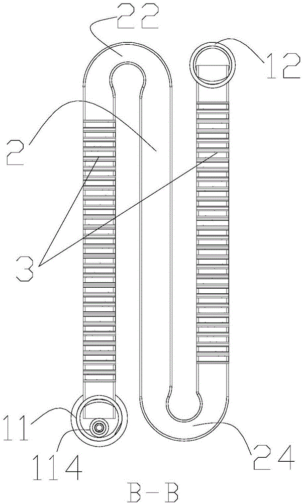
[0026] figure 2 is a structural schematic diagram of a heat exchanger according to an embodiment of the present invention, image 3 yes figure 1 B-B cross-sectional schematic diagram of ; Figure 4 yes figure 1 A-A cross-sectional schematic diagram. The heat exchanger of the present invention can be used in air-conditioning systems to adjust the temperature of the supply air, and can also be used in other equipment for adjusting the temperature of the air passing through the heat exchanger.

[0027] In the air conditioning system, it includes a compress...


PUM


Abstract

The invention discloses a heat exchanger. The heat exchanger comprises a first collecting pipe, a second collecting pipe, a plurality of flat pipes arranged between the first collecting pipe and the second collecting pipe in parallel, and fins arranged in gaps between each two adjacent flat pipes, each flat pipe comprises two bending sections enabling a channel in the flat pipe to divert, the bending sections are a first bending section and a second bending section, the flat pipe also comprises a first linear section, a second linear section, and a third linear section, two sides of the first linear section and the third linear section are provided with the fins, and two sides of the second linear section are provided with the fins. According to the heat exchanger, the folding flat pipe is employed, the re-distribution of refrigerants is avoided, the fins are only arranged at the outsides of the linear sections of the flat pipes in which the refrigerants flow from bottom to top, the heat exchange performance is good, and the wind resistance is small.

Description

technical field [0001] The invention relates to a heat exchanger and belongs to the technical field of heat exchangers. Background technique [0002] In recent decades, the air-conditioning industry has developed rapidly, and heat exchangers are one of the main components of air-conditioning, and various types of heat exchangers have appeared according to market requirements. The parallel flow heat exchanger has the characteristics of high refrigeration efficiency, small size, light weight, and strong pressure resistance, which can well meet the requirements of the market. [0003] The parallel flow heat exchanger is mainly composed of microchannel flat tubes, cooling fins and headers. There are headers at both ends of the microchannel flat tubes for distributing and collecting refrigerant. Corrugated or louver-shaped cooling fins are arranged between adjacent microchannel flat tubes to enhance the heat exchange efficiency between the heat exchanger and the air side. In o...

Claims


Application Information

Patent Timeline
Patent Type & Authority Applications(China)
IPC IPC(8): F25B39/00
CPCF25B39/00
Inventor 不公告发明人
Owner HANGZHOU SANHUA RES INST CO LTD
Why Eureka
Try Eureka