
Test system and test method for open-end winding permanent magnet synchronous motor

A permanent magnet synchronous motor, open winding technology, used in motor generator testing and other directions

Inactive Publication Date: 2015-09-30
JILIN UNIV
View PDF10 Cites 19 Cited by
  • Summary
  • Abstract
  • Description
  • Claims
  • Application Information

AI Technical Summary

Problems solved by technology

[0004] In summary, the existing motor test bench system cannot meet the requirements for effective and comprehensive testing of open-winding permanent magnet synchronous motors, and it is necessary to redevelop a test bench system and test method for this type of motor

Method used


Image

  • Test system and test method for open-end winding permanent magnet synchronous motor
  • Test system and test method for open-end winding permanent magnet synchronous motor
  • Test system and test method for open-end winding permanent magnet synchronous motor

Examples


Embodiment 1

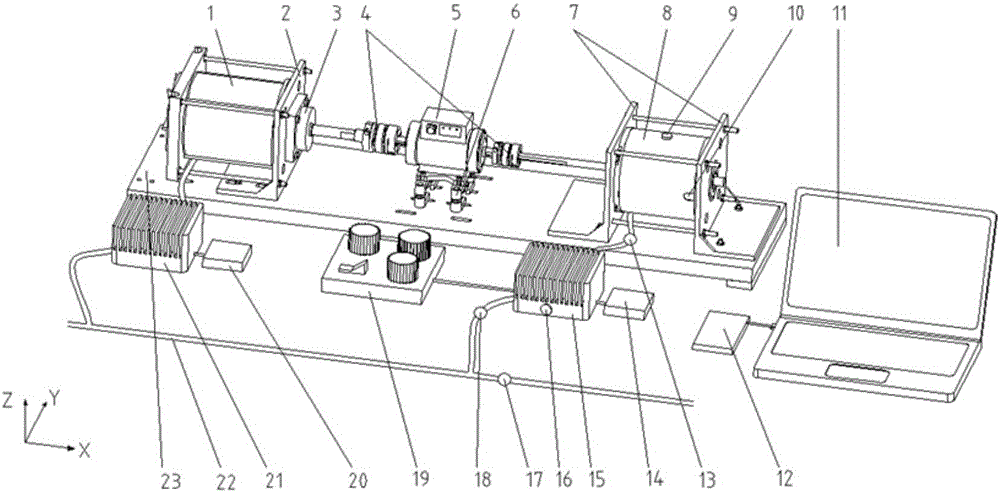
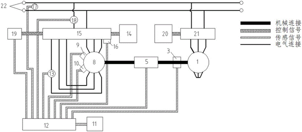
[0054] refer to figure 1 , 2 , a permanent magnet synchronous motor test system with open windings, comprising a permanent magnet synchronous load motor 1 and a tested open winding drive motor 8 arranged at both ends of a frame 23 through a load motor support 2 and a drive motor support 7 respectively, The torque sensor support 6 is arranged on the torque sensor 5 between the permanent magnet synchronous load motor 1 and the measured open winding drive motor 8. The output shaft of the winding drive motor 8 is connected to the output shaft of the permanent magnet synchronous load motor 1, the resolver 3 set on the output shaft of the permanent magnet synchronous load motor 1, the permanent magnet synchronous load motor 1 and the tested open winding drive motor 8 The load motor controller 20 connected to the load motor inverter 21 and the driver connected to the drive motor inverter 15 are respectively connected in parallel to the DC bus 22 through the load motor inverter 21 an...

Embodiment 2

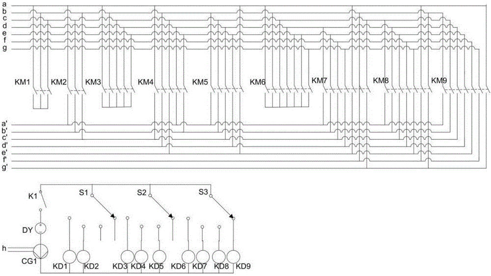
[0064] Based on the open-winding permanent magnet synchronous motor test system described in Embodiment 1, the test method for the open-winding permanent magnet synchronous motor includes working area calculation, fixed winding test and variable winding test. The specific methods are as follows:

[0065] The working area of ​​the motor in each winding state is obtained by calculating the working area (refer to Figure 8 ):

[0066] 1) Read the number of motor phases m, the maximum power P, the maximum torque Tmax0 of the motor in the star winding state, the initial speed n0 and the maximum speed nmax0 of the constant power area;

[0067] 2) Calculate the number of winding states the motor has

[0068] 3) Let the number i of the current motor winding state take 1~(k-1) respectively, then the maximum torque of the motor in the i-th winding state is The starting speed of the constant power zone of the motor is The maximum speed of the motor is n max...


PUM


Abstract

The invention relates to a test system and a test method for an open-end winding permanent magnet synchronous motor. The test system comprises a conventional test system comprising a permanent magnet synchronous load motor and a to-be-tested open-end winding driving motor which are coaxially connected through a torque sensor, a piezoelectric acceleration sensor added to a casing of the to-be-tested open-end winding driving motor, a temperature sensor, a driving motor inverter temperature sensor arranged on a casing of a driving motor inverter as well as a manual control panel connected onto the driving motor inverter in parallel, wherein the torque sensor, a rotating transformer, a driving motor temperature sensor, the driving motor inverter temperature sensor, the piezoelectric acceleration sensor, a driving motor current sensor, a driving motor inverter current sensor and a power voltage sensor are in communication connection with a data acquisition card respectively. The test system and the test method can switch the winding state of the open-end winding motor dynamically in real time and can measure motor vibration and torque fluctuation of the motor as well as temperature increase of motor and inverter systems in a switching process.

Description

technical field [0001] The invention relates to a test bench device of an open winding permanent magnet synchronous motor and a method for testing the working performance of the open winding permanent magnet synchronous motor based on the testing device. Background technique [0002] In recent years, new energy vehicles such as hybrid electric vehicles, pure electric vehicles and fuel cell vehicles are booming. In new energy vehicles, electric drive technology using electric motors as the power source has been widely used, and more stringent requirements have been put forward for vehicle power motors, which has prompted the birth of various new motors and electric drive technologies. A new type of motor developed from permanent magnet synchronous motor - open winding permanent magnet synchronous motor is one of them. The motor has all the advantages of the permanent magnet synchronous motor, and is more flexible in control than the permanent magnet synchronous motor, and ha...

Claims


Application Information

Patent Timeline
IPC IPC(8): G01R31/34
Inventor 许楠贾一帆初亮郭建华赵迪李育宽管国民王严伟
Owner JILIN UNIV
Learn More