
Real beam scanning radar angle super-resolution imaging method based on sparse constraint

A scanning radar, angular super-resolution technology, applied in radio wave measurement systems, radio wave reflection/re-radiation, utilization of re-radiation, etc.

Active Publication Date: 2015-09-30
UNIV OF ELECTRONICS SCI & TECH OF CHINA
View PDF4 Cites 22 Cited by
  • Summary
  • Abstract
  • Description
  • Claims
  • Application Information

AI Technical Summary

Problems solved by technology

However, the noise assumed by this method obeys the Poisson distribution characteristics and does not conform to the actual radar imaging characteristics, so the imaging performance of the algorithm will drop sharply at low signal-to-noise ratios

Method used


Image

  • Real beam scanning radar angle super-resolution imaging method based on sparse constraint
  • Real beam scanning radar angle super-resolution imaging method based on sparse constraint
  • Real beam scanning radar angle super-resolution imaging method based on sparse constraint

Examples


Embodiment Construction

[0084] The technical solution of the present invention will be further described below in conjunction with the accompanying drawings, but the content protected by the present invention is not limited to the following description.

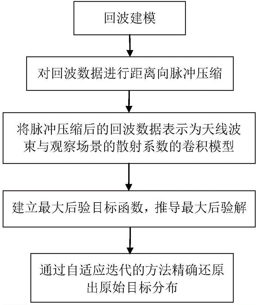
[0085] like figure 1 As shown, a real-beam scanning radar angle super-resolution imaging method based on sparse constraints includes the following steps:

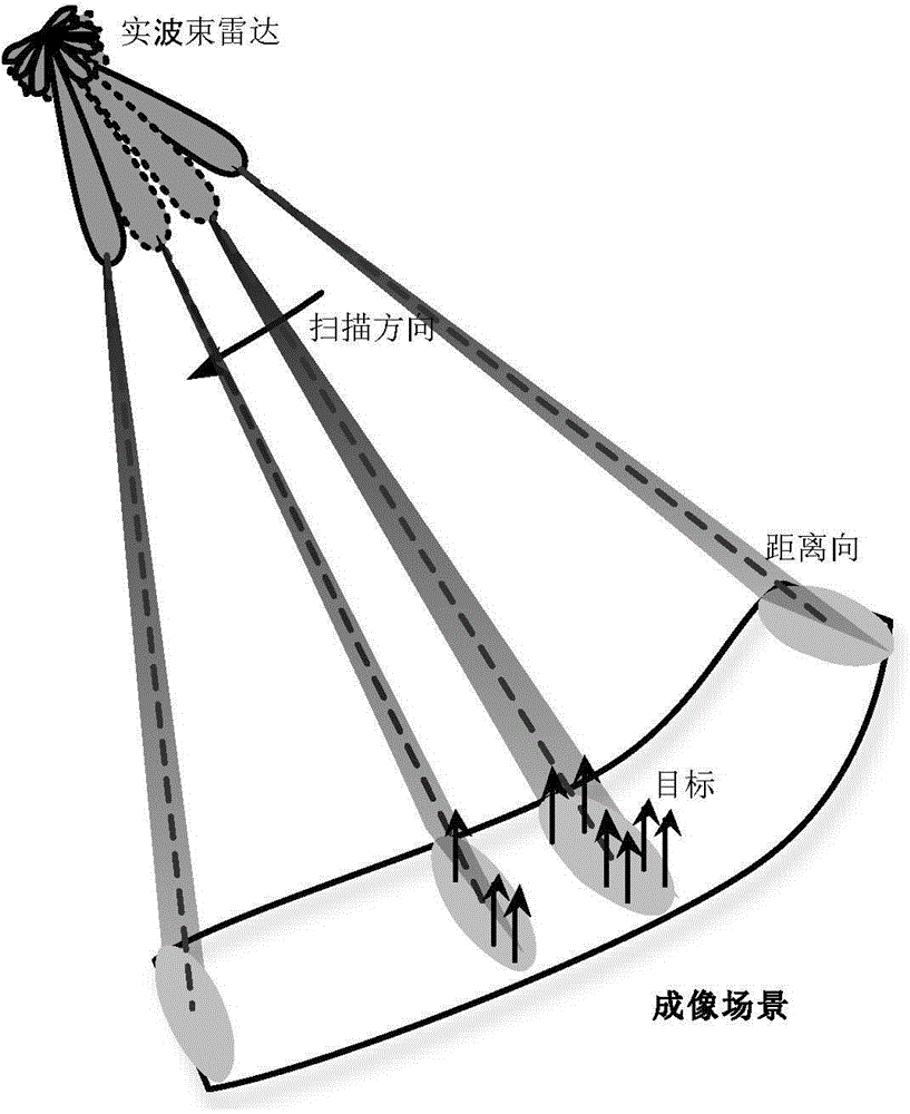
[0086] S1. Echo modeling, based on the geometric relationship between the real beam scanning radar and the target, the echo data model of the scanning radar is established; the specific implementation method is: the radar is at a height H below the angle of view Scan the -ψ~ψ imaging area clockwise; at the initial moment, the initial slant distance between the radar antenna and the target at the center of the scene is r 0 , let the corresponding coordinates of each target point in the scene be (x i ,y i ), the azimuth angle between each target and the radar corresponds to θ i , the slant dis...


PUM


Abstract

The invention discloses a real beam scanning radar angle super-resolution imaging method based on sparse constraint. The real beam scanning radar super-resolution imaging method comprises the following steps of S1 performing echo modeling, and establishing an echo data model of a scanning radar on the basis of a geometrical relationship of a real beam scanning radar and a target; S2 performing range pulse compression on echo data, so as to realize range high resolution; S3 expressing the echo data after pulse compression to a convolution model of scattering coefficients of an antenna beam and an observation scene; S4 establishing a maximum posterior objective function according to the convolution model obtained in the step S3, and deducing a maximum posterior solution; S5 precisely reducing original target distribution through an adaptive iteration method. According to the real beam scanning radar angle super-resolution imaging method, clutter characteristics are expressed by using rayleigh distribution, target distribution characteristics are reflected by utilizing the sparse constraint, target distribution is inverted, and additionally, the influence of noise on imaging results is inhibited, so that radar angle super resolution processing results are close to actual target distribution, and real beam scanning radar angle super-resolution imaging is realized.

Description

technical field [0001] The invention belongs to the technical field of radar imaging, and in particular relates to a real-beam scanning radar angle super-resolution imaging method based on sparse constraints. Background technique [0002] The high-resolution imaging of real beam scanning radar has great application value in the fields of ship navigation, tower monitoring and remote early warning. At the same time, this imaging mode also has the advantages of small size and low cost, so this imaging mode has broad application prospects. The real-beam scanning radar successively irradiates the imaging area at a fixed scanning speed, transmits a linear frequency modulation signal (LFM) and receives the echo signal to obtain a two-dimensional echo signal of the radar active area. Since the transmitted signal dimension is an LFM signal, high range resolution can be achieved by using pulse compression technology. In azimuth, the real beam azimuth resolution is given by decision...

Claims


Application Information

Patent Timeline
Patent Type & Authority Applications(China)
IPC IPC(8): G01S13/89G01S7/41
CPCG01S7/41G01S13/89
Inventor 张寅王月黄钰林查月波武俊杰杨建宇
Owner UNIV OF ELECTRONICS SCI & TECH OF CHINA
Learn More