
Middle-far-infrared image simulation device

An infrared image and simulation device technology, applied in simulators, image analysis, image data processing and other directions, can solve the problems of uniform heat distribution, confuse passive infrared detection equipment, etc. Advanced effect of technical indicators

Inactive Publication Date: 2015-09-30
北京云创太和科技有限公司
View PDF0 Cites 5 Cited by
  • Summary
  • Abstract
  • Description
  • Claims
  • Application Information

AI Technical Summary

Problems solved by technology

At present, most false targets on the market only use a single heat source to simulate the heat distribution characteristics of the real target’s heat-generating components when simulating the infrared radiation characteristics of the real target. The heat distribution on the shell of the real target is not as uniform as a single heat source, so it is risky to use a single heat source to simulate the heat distribution of the heat-generating components on the shell. The image of the infrared detection and the infrared detection image of the real target There are differences, and they cannot perfectly confuse the enemy's passive infrared detection equipment

Method used


Image

  • Middle-far-infrared image simulation device
  • Middle-far-infrared image simulation device
  • Middle-far-infrared image simulation device

Examples


Embodiment 1

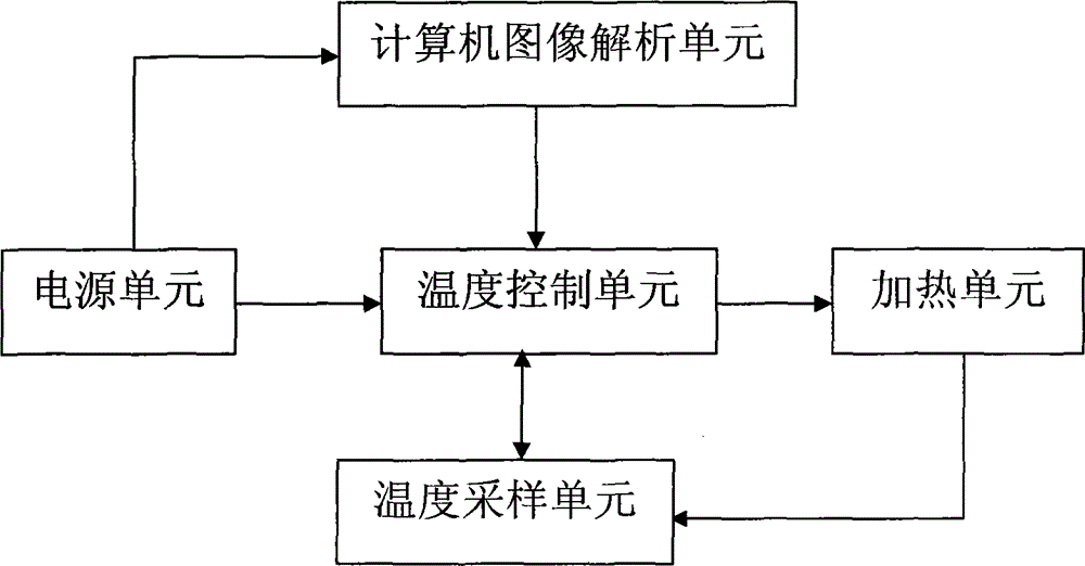
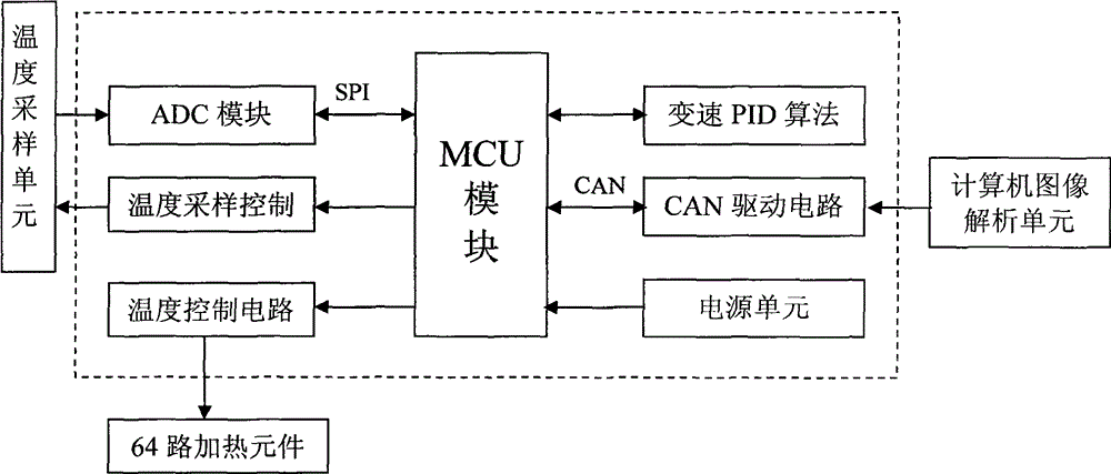
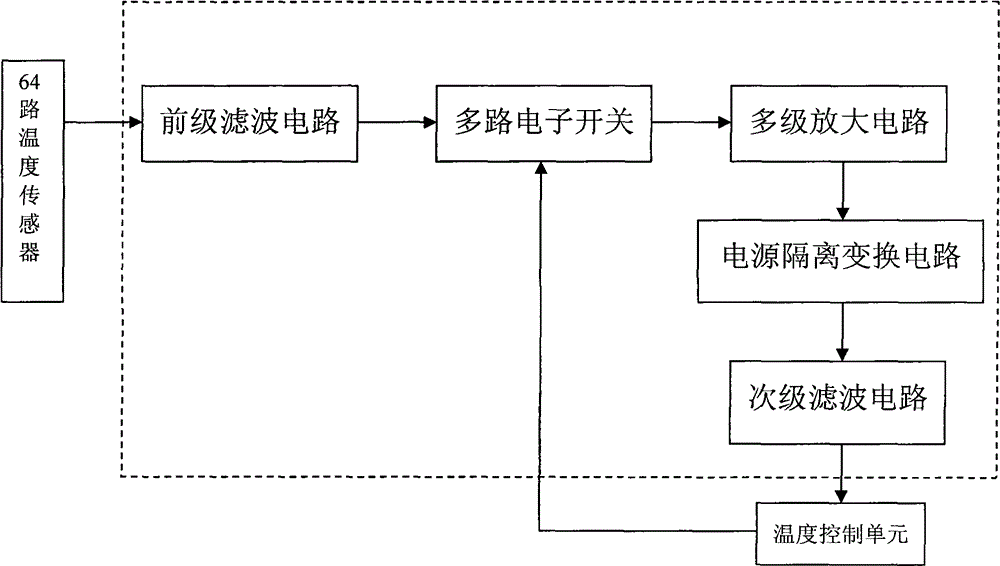
[0023] Such as figure 1 It is the overall schematic diagram of the mid-to-far infrared simulation device, including five parts: power supply unit, heating unit, temperature control unit, temperature sampling unit and computer image analysis unit. Wherein the heating unit is arranged inside the rubber plate inlaid with circular iron sheets; the units are connected by wires. In the present invention, the infrared image that has been imported into the system is firstly analyzed by the computer image analysis unit, and the analyzed temperature data information is transmitted to the temperature control unit, and then the temperature control unit performs heating control on the heating unit according to the obtained data information , and decided to turn on an electronic switch in the temperature sampling unit to implement temperature detection, and then the temperature sampling unit will transmit the sensed micro-signal to the temperature control unit, and finally realize the tempe...

Embodiment 2

[0028]In this embodiment, the software system in the computer image analysis unit is modulated so that the image can be analyzed into 81 equal parts on average, and the temperature control unit and the temperature sampling unit are improved accordingly, and the heating elements of the heating unit are increased to 9 ×9, it can realize the temperature control of 81 channels, so as to make a more detailed simulation of the known infrared images.


PUM


Abstract

The invention relates to a middle-far-infrared image simulation device. The device comprises a power unit, a heating unit, a temperature control unit, a temperature sampling unit, and a computer image analysis unit. The heating unit is disposed in a rubber slab provided with a circular iron sheet in an inset manner. The above units are connected with each other through wires. The computer image analysis unit is used for the analysis of an infrared image led into a system, and enables the analyzed data information to be transmitted to the temperature control unit. The temperature control unit carries out the heating control of the heating unit according to the obtained data information, and determines the turning-on of one electronic switch in the temperature sampling unit to carry out temperature detection. Afterwards, the temperature sampling unit can enable the induced miniature signal to be transmitted to the temperature control unit, thereby finally achieving a purpose that the temperature control unit achieves the control of the heating unit according to the data information analyzed by the computer image analysis unit, and completing the projection of the infrared image. The device is reasonable in design, is advanced in idea, and is adapted to wide application.

Description

technical field [0001] The invention relates to a mid-to-far infrared image simulation device, in particular to a mid-to-far infrared image simulation device for false targets. Background technique [0002] Reconnaissance and counter-reconnaissance seem to be the eternal topics of human warfare, and since the popularity of reconnaissance aircraft during World War I, there are almost no secrets on the battlefield that can be hidden. In order to avoid the enemy's aerial reconnaissance, people have come up with various methods, and there are two more feasible ones: one is "hiding" and "hiding"; the other is using "false targets" to confuse the public. And this second trick was used in different ways during World War II. [0003] Air reconnaissance during World War II relied on the pilot's naked eyes and optical cameras. Pilots often only rely on "feeling" when observing ground targets. Even if they use a camera to take pictures of the target, it is still extremely difficult t...

Claims


Application Information

Patent Timeline
Patent Type & Authority Applications(China)
IPC IPC(8): G06T7/00G05B17/02
Inventor 刘云鹏朱阳春
Owner 北京云创太和科技有限公司
Learn More