
Blanking circuit

A technology of blanking circuits and resistors, applied in instruments, static indicators, etc., can solve the problem of lack of filtering in blanking circuits, and achieve the effect of improving display effect, ensuring reliability and improving compatibility.

Inactive Publication Date: 2015-09-30
SUZHOU HEXINMEI ELECTRONICS SCI & TECH CO LTD
View PDF5 Cites 0 Cited by
  • Summary
  • Abstract
  • Description
  • Claims
  • Application Information

AI Technical Summary

Problems solved by technology

[0014] The technical problem to be solved by the present invention is to provide a blanking circuit, which solves the problem of screen flicker caused by the lack of filtering in the blanking circuit in the prior art

Method used


Image

  • Blanking circuit
  • Blanking circuit

Examples


Embodiment 1

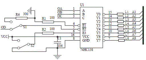
[0030] Embodiment 1, the decoder is 74HC138, the common end of the first selection switch S1 is connected to the second contact of the first selection switch S1; the common end of the second selection switch S2 is connected to the second contact of the second selection switch S1 The first contact of S2 is connected.

[0031] 74HC138 plays the role of row selection control in the LED display module. 74HC138 is a high-speed CMOS device. 74HC138 pins are compatible with low-power Schottky TTL (LSTTL) series.

[0032] The 74HC138 decoder accepts 3-bit binary weighted address inputs (A0, A1, and A2) and, when enabled, provides 8 mutually exclusive active-low outputs (Y0 to Y7). The 74HC138 has 3 enable inputs: two active low (E1 and E2) and one active high (E3). The 74HC138 will keep all outputs high unless E1 and E2 are driven low and E3 is driven high. Utilizing this composite enabling feature, only four 74HC138 chips and one inverter are needed to easily realize parallel expan...

Embodiment 2

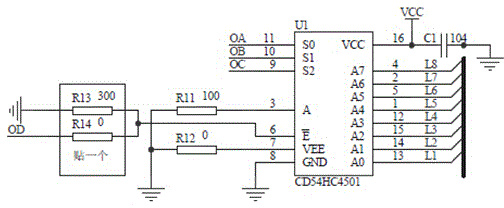
[0033] Embodiment 2, the decoder is CD54HC4051, the common end of the first selection switch S1 is connected to the second contact of the first selection switch S1; the common end of the second selection switch S2 is connected to the second contact of the second selection switch S2 The second contact of S2 is connected. Different decoder ICs have different level states corresponding to the connection to the enable end, and the level state can be selected through the selection switch, which facilitates the application of various ICs. The switching of each state can be completed without disassembling the resistor, which saves manpower and material resources and ensures the reliability of the LED product PCB.

[0034] Both the first selection switch S1 and the second selection switch S2 are single-pole double-throw switches or dial switches.

[0035] When the system with the OD control signal is selected, the common end of the first selection switch S1 is connected to the second...


PUM


Abstract

The invention discloses a blanking circuit. The blanking circuit comprises a decoder, a capacitor, first to third resistors, a first option switch and a second option switch, wherein the decoder comprises first to third enable ends; each of the first option switch and the second option switch comprises a common end, a first contact and a second contact; a magnetic bead is connected with each of first to eighth ends of the decoder in series; enable ends of different decoder ICs (integrated chips) are correspondingly connected with different level states, the level states are selected through the option switches, and application of the various ICs is facilitated. Different enable signals are provided by different system control, and whether enable signals provided by a system are adopted or not is selected through the option switches, so that the system application compatibility is improved; the magnetic beads are connected onto output signals in series, transmission of the signals is not affected, clutter interference on the signals can be effectively filtered out, the display effect of a display screen is improved, and running is more stable.

Description

technical field [0001] The invention discloses a blanking circuit, in particular to an LED display blanking circuit, which belongs to the field of LED display application circuits. Background technique [0002] A phenomenon that has always existed in the LED display industry is smearing and caterpillars. Major controller manufacturers continue to improve this phenomenon. Smearing will appear before and after smearing. It will cause a problem of section capacitor itself, and it will also act as a capacitor, which is the front blanking; the so-called rear smear: that is, the line tube 4953 double P-channel-MOS tube, when working, there is a 5V to 0V switch on and off, In the process of reducing the voltage, there will be a dark and bright smear of the forward voltage drop of the LED in the (N-1) row. [0003] For the post-blanking situation, when designing the circuit, the 4953 on (row N-1) will be discharged, that is, the blanking circuit will be added. At present, there are...

Claims


Application Information

Patent Timeline
Patent Type & Authority Applications(China)
IPC IPC(8): G09G3/32
Inventor 朱霞高珺胡国良
Owner SUZHOU HEXINMEI ELECTRONICS SCI & TECH CO LTD
Learn More