X-ray generator

A technology for generating devices and X-rays, used in X-ray tubes, X-ray tubes, X-ray equipment, etc., to achieve the effect of prolonging life

Inactive Publication Date: 2015-09-30
SHIMADZU SEISAKUSHO CO LTD
View PDF6 Cites 4 Cited by
  • Summary
  • Abstract
  • Description
  • Claims
  • Application Information

AI Technical Summary

Problems solved by technology

[0004] In contrast, in Figure 5 In the shown sealed type X-ray generator, the X-ray irradiation window 504 integrally forming the target is airtightly fixed to the vacuum vessel 501 by welding or brazing, and therefore cannot be rotated as described above.

Method used


Image

  • X-ray generator
  • X-ray generator
  • X-ray generator

Examples


Embodiment Construction

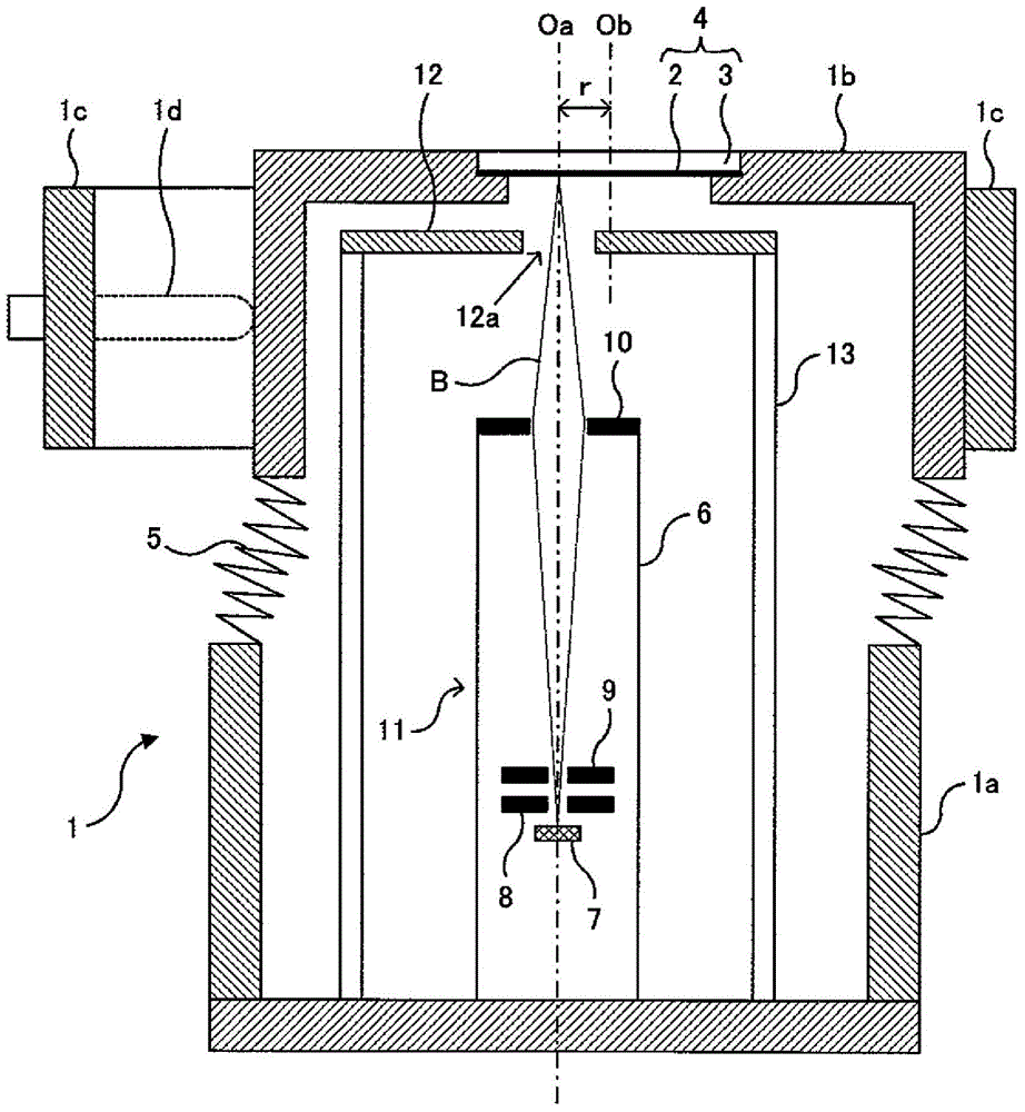
[0058] Hereinafter, embodiments of the present invention will be described with reference to the drawings. figure 1 It is a schematic sectional view of embodiment of this invention.

[0059] The vacuum vessel 1 is of a sealed type, and a target member 4 in which a film-shaped target 2 and an X-ray irradiation window 3 are integrally formed is fixedly attached to the top thereof. This vacuum container 1 constitutes a container movable portion 1 b in which a portion including an upper side where the target member 4 is disposed is connected to a lower container main body portion 1 a by a connecting member 5 . The connecting member 5 is a member capable of parallel movement of the container movable portion 1b relative to the container main body 1a, in other words, in a direction perpendicular to the central axis Oa of the container main body 1a, such as a welded bellows.

[0060] The positioning stopper 1c surrounding the periphery of the container movable part 1b is provided in...


PUM


Abstract

An X-ray generator is provided using a transmission type target having a long life span, where it is possible to change the point for generating X-rays on the surface of the target while maintaining the vacuum chamber in a high vacuum state. A portion of a vacuum chamber 1 that includes a target 2 is linked to a main body portion 1a of the chamber through a linking member 5 as a movable chamber portion 1b. A fixed anode 12 is provided between the target 2 and the electrode 10 at the final stage from among a group of electrodes 8, 9 and 10 for electrostatically accelerating and converging electrons from an electron source 7 and is fixed to the main body portion 1a of the chamber in order to prevent the form of the electrical field from changing when the movable chamber portion 1b is shifted.

Description

technical field [0001] The present invention relates to an X-ray generating device used in an industrial X-ray inspection device or a medical X-ray inspection device, or various X-ray analysis devices or measurement devices using X-ray diffraction or refraction, and more specifically In other words, it relates to a transmission type X-ray generator that emits X-rays generated by colliding electrons against a target in a vacuum container to the outside of the vacuum container centering on a direction along the direction in which the electrons advance. Background technique [0002] There are two types of X-ray generators that generate X-rays by colliding electrons against a target in a vacuum container. One uses a reflective target that emits X-rays in a direction different from the direction in which electrons travel; A transmission type target that emits X-rays in approximately the same direction as electrons travel. A transmission type target is usually formed of a thin fi...

Claims


Application Information

Patent Timeline
Patent Type & Authority Applications(China)
IPC IPC(8): H01J35/08H01J35/16
CPCH01J2235/087H01J35/14H01J35/28H01J35/116H01J35/147H01J1/40H01J1/88H01J5/02H01J5/04H01J19/56H01J35/186A61B6/40A61B6/44A61B2560/0406H01J35/02H01J35/04H01J35/16H01J37/16H01J2235/083H01J2235/16H01J2235/163H05G1/02H05G1/04
Inventor 宫冈明宽
Owner SHIMADZU SEISAKUSHO CO LTD
Why Eureka
Try Eureka