Low-speed and high-torque motor with magnetic gear

A magnetic gear, high torque technology, applied in the direction of magnetic circuit rotating parts, synchronous motors with static armatures and rotating magnets, magnetic circuit static parts, etc., can solve the problem of increasing the cost of the motor and increasing the outer gas gap length, reducing the coupling degree between the magnetic field of the armature group and the permanent magnetic field of the inner rotor, etc.

Inactive Publication Date: 2015-09-30
SOUTH UNIVERSITY OF SCIENCE AND TECHNOLOGY OF CHINA
View PDF5 Cites 8 Cited by
  • Summary
  • Abstract
  • Description
  • Claims
  • Application Information

AI Technical Summary

Problems solved by technology

[0004] In the prior art, the magnetic gears, one of the important components of the magnetic gear low-speed high-torque motor, are all permanent magnet excitations, that is, permanent magnets are installed in the stator, so on the one hand, a large number of permanent magnets must be used, increasing the On the other hand, according to the working principle of the magnetic gear low-speed high-torque motor, the magnetic field generated by the armature winding interacts with the magnetic field of the inner rotor permanent magnet to drive the inner rotor to rotate, which in turn drives the magnetic gear's magnetic ring to rotate , therefore, the permanent magnets in the stator will inevitably increase the length of the outer air gap, reduce the coupling degree of the magnetic field of the armature group and the permanent magnetic field of the inner rotor, and reduce the torque output capability of the composite motor

Method used


Image

  • Low-speed and high-torque motor with magnetic gear
  • Low-speed and high-torque motor with magnetic gear
  • Low-speed and high-torque motor with magnetic gear

Examples


Embodiment Construction

[0018] The present invention will be further described in detail below through specific embodiments in conjunction with the accompanying drawings.

[0019] In this application document, unless otherwise specified, the orientation words used such as "upper and lower" usually refer to the upper and lower as shown in the drawings; The inside and outside of the silhouette.

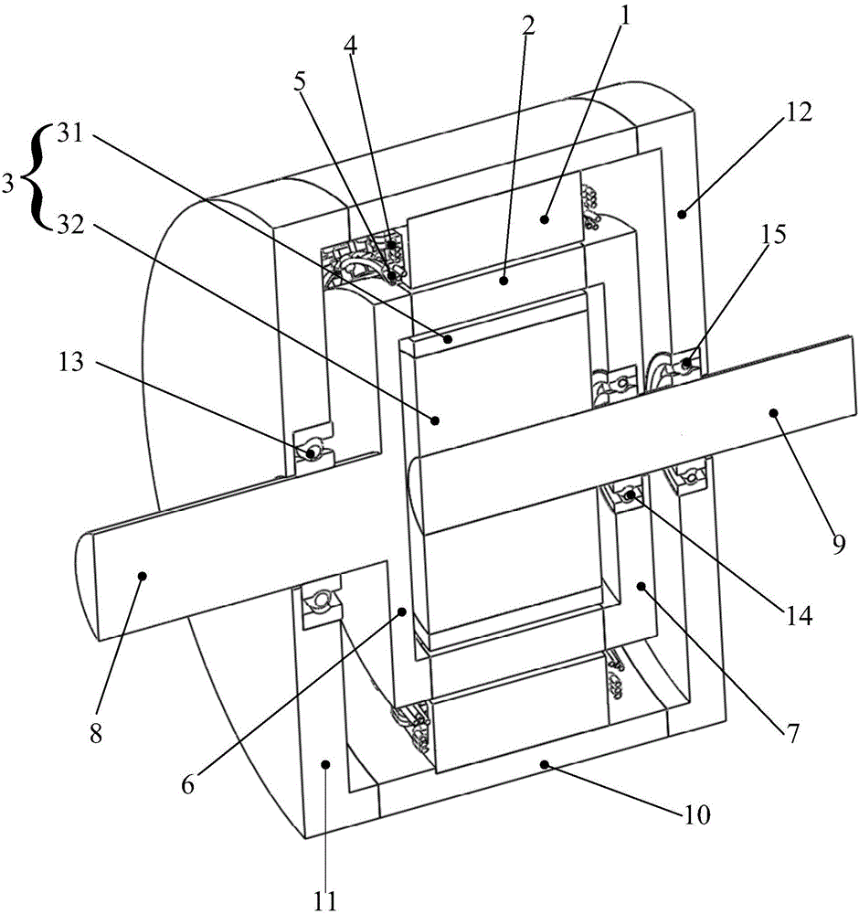
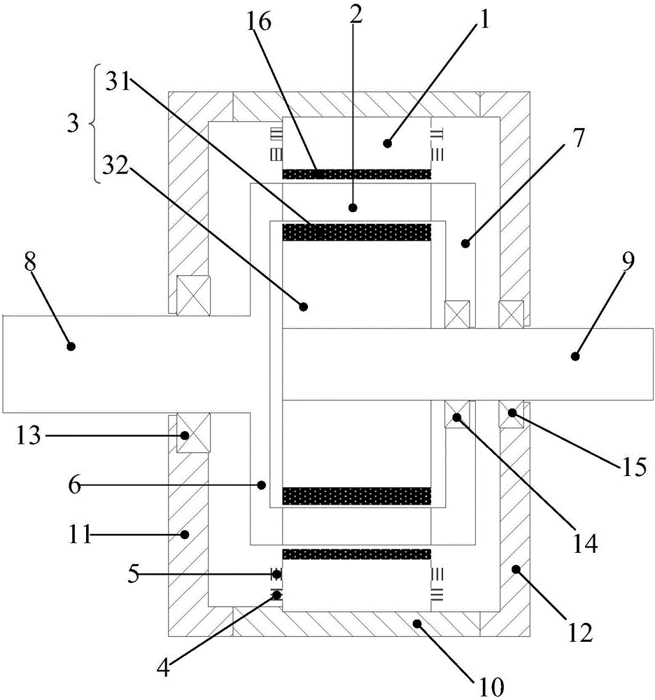
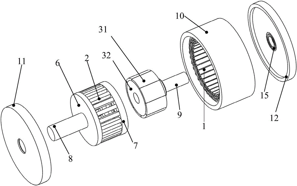
[0020] Please refer to Figure 1a and Figure 1b , is a planing structure schematic diagram and a plane structure schematic diagram of a magnetic gear low-speed high-torque motor disclosed in this embodiment. The magnetic gear low-speed high-torque motor includes: an inner rotor 3 arranged coaxially from the inside to the outside, and a magnetization ring 2 and stator 1. Wherein, the inner rotor 3 is provided with a permanent magnet; the stator 1 is provided with an armature winding 5 that generates a rotating magnetic field, and the stator 1 is also provided with an electromagnet 4 that generates a constant...


PUM


Abstract

The invention provides a low-speed and high-torque motor with a magnetic gear. The low-speed and high-torque motor comprises an inner rotor, an adjustable magnetic ring and a stator which are coaxially and sequentially arranged from inside to outside, wherein a permanent magnet is arranged in the inner rotor; an armature winding for generating a rotating magnetic field and an electromagnet for generating a constant magnetic field are arranged in the stator. By adopting the electromagnet to generate the constant magnetic field in the stator and to replace a permanent magnet in the stator, the usage of the permanent magnet can be reduced, so that the length of an air gap on an outer layer is reduced, and further the coupling degree of an armature winding magnetic field and a permanent magnet magnetic field of the inner rotor is improved.

Description

technical field [0001] The invention relates to the field of power transmission equipment, in particular to a magnetic gear low-speed high-torque motor. Background technique [0002] Direct drive low-speed high-torque motors are in great demand in many occasions, such as wind power generation, ship propulsion and other technical fields. In traditional power equipment, high-speed motors are often used to drive multi-stage reduction gearboxes. The reduction gearbox generally adopts a mechanical gearbox, which relies on the meshing between teeth to transmit torque. It is a contact transmission method, and its work often requires an oil-lubricated environment. After overloading, the gears are easy to break, so regular maintenance is required. In addition, the reduction gearbox used is relatively large in size and weight, and it is used in conjunction with a high-speed motor. The two together take up more space and are heavier. [0003] Since the appearance of magnetic gears, ...

Claims


Application Information

Patent Timeline
Patent Type & Authority Applications(China)
IPC IPC(8): H02K21/14H02K1/27H02K1/12
Inventor 蹇林旎石玉君尉进邓正兴
Owner SOUTH UNIVERSITY OF SCIENCE AND TECHNOLOGY OF CHINA
Why Eureka
Try Eureka