Wind power plant gear mechanism

A technology of wind equipment and transmission mechanism, applied in wind turbines, wind turbine components, engines, etc., can solve the problems of uncommercialization, sliding bearing migration, etc., to prevent offset, prevent axial migration, and improve position fixity Effect

Active Publication Date: 2015-09-30
MIBA SINTER AUSTRIA
View PDF10 Cites 7 Cited by
  • Summary
  • Abstract
  • Description
  • Claims
  • Application Information

AI Technical Summary

Problems solved by technology

Problems often arise in these bearings: the outer ring of the bearing rotates due to the cyclic, periodic load, and due to the additional axial force, the rolling bearing also leaves its rated position axially and migrates
[0003...

Method used


Image

  • Wind power plant gear mechanism
  • Wind power plant gear mechanism
  • Wind power plant gear mechanism

Examples


Embodiment Construction

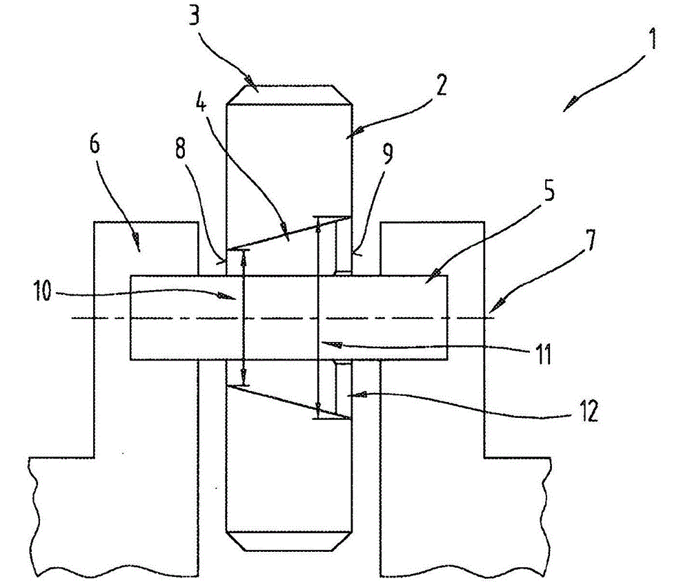
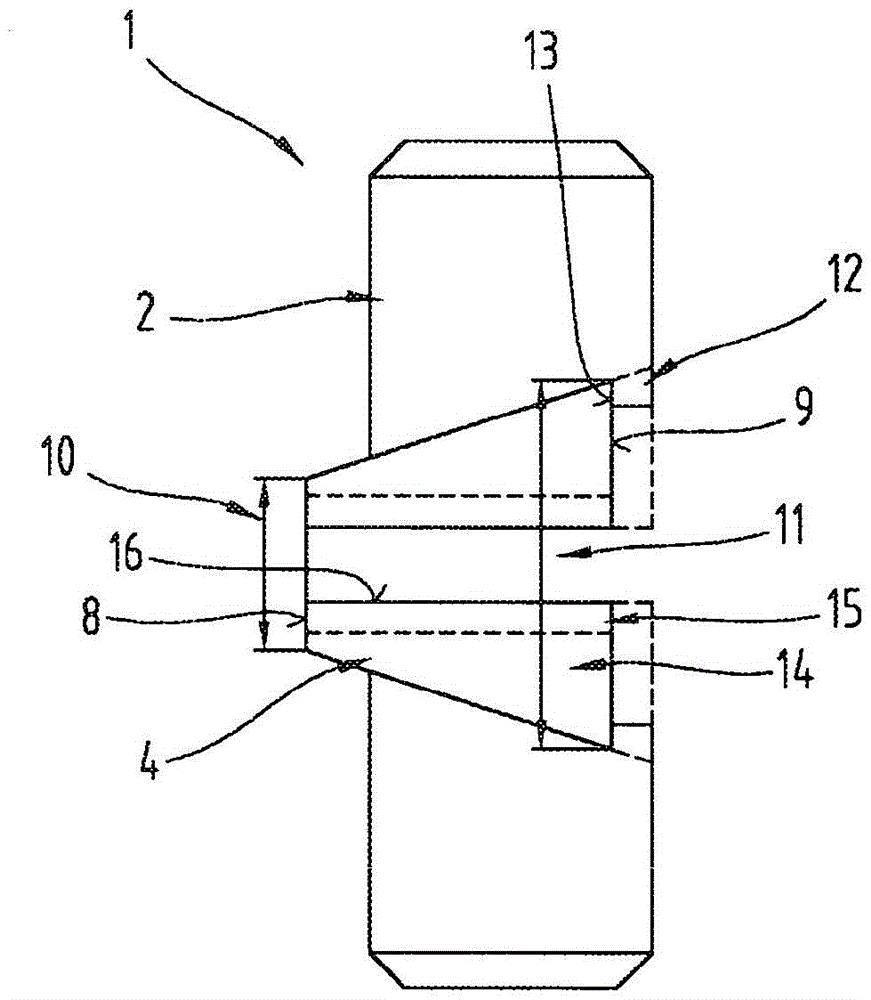
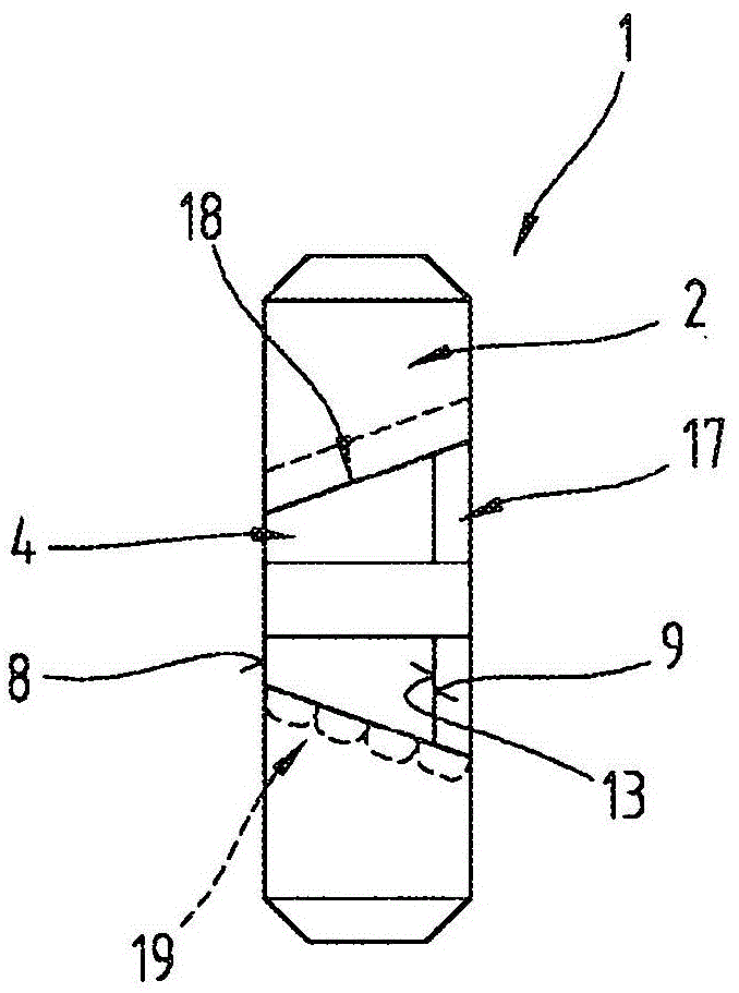
[0025] As an introduction, it should first be explained that in the various embodiments described in different descriptions, the same components are configured with the same reference numerals or the same component names, and the disclosure contained in the entire description can be transferred to the configurations according to the meaning. On the same part with the same reference number or the same component name. Furthermore, the orientation descriptions selected in the specification, such as up, down, side, etc., are relative to the direct description and shown drawings, and when the orientation changes, they can be transferred to the new orientation according to the meaning .

[0026] As is known, a wind power installation comprises a tower at the upper end of which a nacelle is arranged, in which nacelle a rotor with rotor blades is mounted. This rotor is operatively connected via a wind power transmission to a generator also located in the nacelle, wherein the low rota...


PUM


Abstract

The invention relates to a wind power plant gear mechanism (1) with an axle (5) and a gearwheel (2), wherein at least one sliding bearing bush (4, 20) is arranged between the axle (5) and the gearwheel (2), and wherein the at least one sliding bearing bush (4, 20) is connected to the gearwheel (2) via a conical press fit, wherein the at least one sliding bearing bush (4, 20) has a first end surface (8) and a second end surface (9) which lies opposite the former along a longitudinal centre axis (7) through the at least one sliding bearing bush (4, 20), and wherein the first end surface (8) has a diameter d (10) and the second end surface (9) has a diameter D (11), wherein the diameter D (11) is greater than the diameter d (10), and wherein a bearing surface (13) for the at least one sliding bearing bush (4, 20) is formed so as to adjoin the end surface (9) with the diameter D (11).

Description

technical field [0001] The invention relates to a transmission mechanism of a wind power installation, which comprises a shaft and a gear, at least one sliding sleeve is arranged between the shaft and the gear, and also relates to a wind power installation with a transmission mechanism of the wind power installation. Background technique [0002] Today, the only commercial solutions for supporting planetary gears in planetary gears of wind power installations are rolling bearing solutions. Problems frequently arise in these bearings: the bearing outer ring rotates due to the cyclic, cyclical load, and the rolling bearing also axially leaves its set position and shifts due to the additional axial force. In order to control this problem, a bearing scheme without an outer ring is proposed. [0003] Plain bearing concepts for planetary gears of wind power installations have likewise been described, but have not hitherto been commercialized. However, sliding bearings also have ...

Claims


Application Information

Patent Timeline
IPC IPC(8): F16H57/08F03D11/00F16C33/10
CPCY02E10/722F03D11/0008F16C17/04F16D1/0858F16C33/1055F05B2260/40311F16H2057/085F16C33/08F16H57/0479F03D15/00Y02E10/72F16C2360/31F16C2361/61F03D80/70Y10T74/1986F16C17/105F16C33/122F16H55/17
Inventor G·哈格J·S·赫茨尔
Owner MIBA SINTER AUSTRIA
Why Eureka
Try Eureka