Casting die

A technology of casting molds and molds, which is applied in the direction of manufacturing tools, casting molding equipment, casting molds, etc., which can solve the problems of low casting quality, long casting manufacturing cycle, and high energy consumption, so as to reduce the difficulty of cleaning work and relieve aluminum leakage. And the effect of bringing flash and reducing manufacturing cost

Inactive Publication Date: 2015-10-07
朱瑞瑞
View PDF5 Cites 3 Cited by
  • Summary
  • Abstract
  • Description
  • Claims
  • Application Information

AI Technical Summary

Problems solved by technology

[0002] The casting mold in the prior art includes an upper mold, a lower mold and a middle mold. The middle mold includes several combined modules. After the upper and lower molds are connected, the modules of the middle mold are respectively pressed on the outer walls of the upper and lower molds by hydraulic cylinders, and then The molten fluid liquid is directly injected into the cavity of the casting mold from the sprue of the casting mold. When the casting is formed, the middle mold is reset, and the upper and lower molds are separated. The casting rises with the upper mold, and the operator sends the tray to the upper mold. Below the mold, the castings fall off on the tray; this kind of mold has more sealing surfaces between each other, the situation of running aluminum and flashing is serious, the waste of raw materials is large, the manufacturing cost is high, and the follow-up cleaning work is difficult. The manufacturing cycle is long, and the mold is fully opened during demoulding, and the temperature of the mold diverges quickly. It takes a long time to reheat the mold for repeated use, and the energy consumption is high
In addition, the defect rate of casting slag inclusion in castings after molding is 30%-40%, the quality of castings is not high, and the yield is low

Method used


Image

  • Casting die
  • Casting die

Examples


Embodiment Construction

[0012] The technical solutions of the present invention will be described in further detail below in conjunction with the accompanying drawings and specific embodiments.

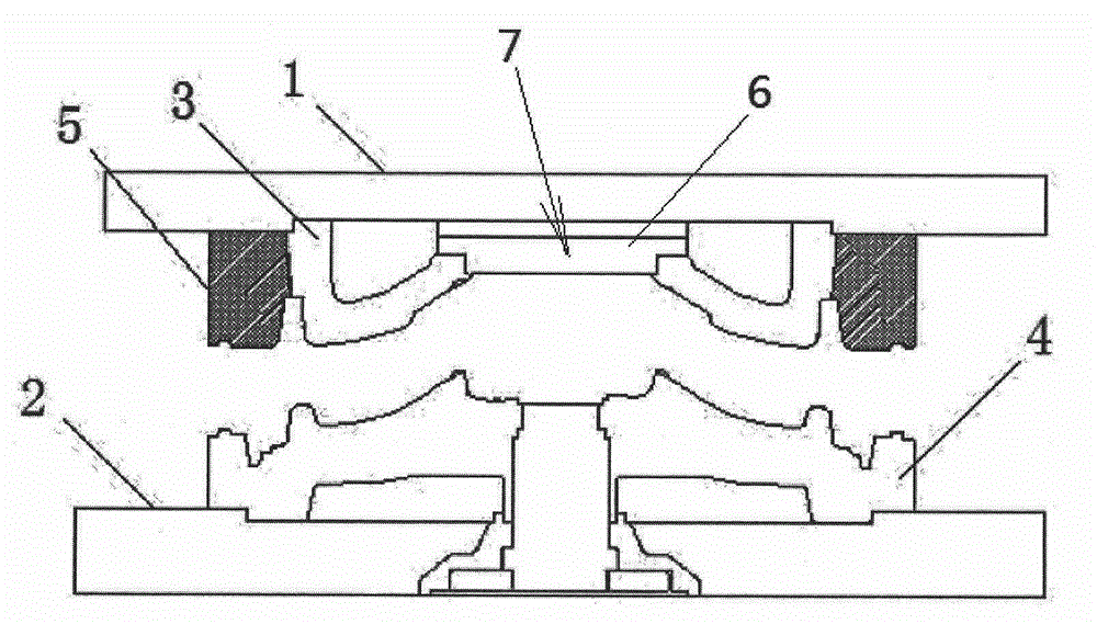
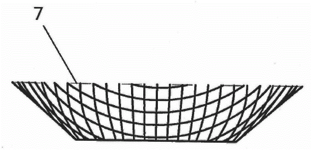
[0013] figure 1 and figure 2 A casting mold provided according to an embodiment of the present invention is schematically shown.

[0014] like figure 1 As shown, in this embodiment of the present invention, the casting mold is a wheel hub manufacturing mold, including an upper mold 3 connected to the upper mold mounting plate 1, a lower mold 4 connected to the lower mold mounting plate 2, and a pouring mold located at the mold 3. Port 6, wherein the upper mold ring 5 is provided on the outer periphery of the upper mold 3, the upper end surface of the upper mold ring 5 is fixedly connected to the upper mold mounting plate 1, the lower end surface formed by the combination of the upper mold ring 5 and the upper mold 3 and the upper end of the lower mold 4 faces match.

[0015] like figure 1 and figure ...


PUM


Abstract

The invention discloses a casting die which comprises an upper die connected to an upper die mounting plate, a lower die connected to a lower die mounting plate, and a sprue gate. The casting die is characterized in that an upper die ring is arranged on the periphery of the upper die, the upper end surface of the upper die ring is fixedly connected to the upper die mounting plate, a lower end surface formed by combination of the upper die ring and the upper die is matched with the upper end surface of the lower die, and a filter device matched with the sprue gate is arranged in the sprue gate. The casting die has the advantages that aluminum spilling and flashing are reduced effectively, raw materials are saved, manufacturing cost of castings is lowered, difficulty of subsequent cleaning work is reduced, and manufacturing cycle of the castings is shortened. As the upper die is encircled by the upper die ring, heat insulation effect is improved obviously, time for reheating the die is shortened greatly, energy consumption is reduced, and manufacturing cost of spokes is lowered. Since the sprue gate is provided with a filter screen, slag inclusion rate of the molded castings is reduced to 5-8%, quality of the molded castings is improved, and yield of the castings is increased.

Description

technical field [0001] The invention relates to the technical field of casting, in particular to a casting mold which avoids aluminum run-off and burrs, and simultaneously improves casting quality and yield. Background technique [0002] The casting mold in the prior art includes an upper mold, a lower mold and a middle mold. The middle mold includes several combined modules. After the upper and lower molds are connected, the modules of the middle mold are respectively pressed on the outer walls of the upper and lower molds by hydraulic cylinders, and then The molten fluid liquid is directly injected into the cavity of the casting mold from the sprue of the casting mold. When the casting is formed, the middle mold is reset, and the upper and lower molds are separated. The casting rises with the upper mold, and the operator sends the tray to the upper mold. Below the mold, the castings fall off on the tray; this kind of mold has more sealing surfaces between each other, the s...

Claims


Application Information

Patent Timeline
Patent Type & Authority Applications(China)
IPC IPC(8): B22C9/00B22C9/08
Inventor 朱瑞瑞
Owner 朱瑞瑞
Why Eureka
Try Eureka