Assembly tooling and assembly method of rotary compressor

A technology for rotary compressors and assembling tooling, which is applied to auxiliary devices, manufacturing tools, metal processing equipment, etc., can solve the problem that the assembly tooling assembly method has not been perfected, and achieves low noise, good reliability, and motor clearance imbalance. small effect

Active Publication Date: 2018-07-17
GUANGDONG MEIZHI COMPRESSOR +1
View PDF8 Cites 0 Cited by
  • Summary
  • Abstract
  • Description
  • Claims
  • Application Information

AI Technical Summary

Problems solved by technology

In actual production, for some new double support structures of rotary compressors, the assembly tooling and corresponding assembly methods have not yet been perfected

Method used


Image

  • Assembly tooling and assembly method of rotary compressor
  • Assembly tooling and assembly method of rotary compressor
  • Assembly tooling and assembly method of rotary compressor

Examples


Embodiment 1

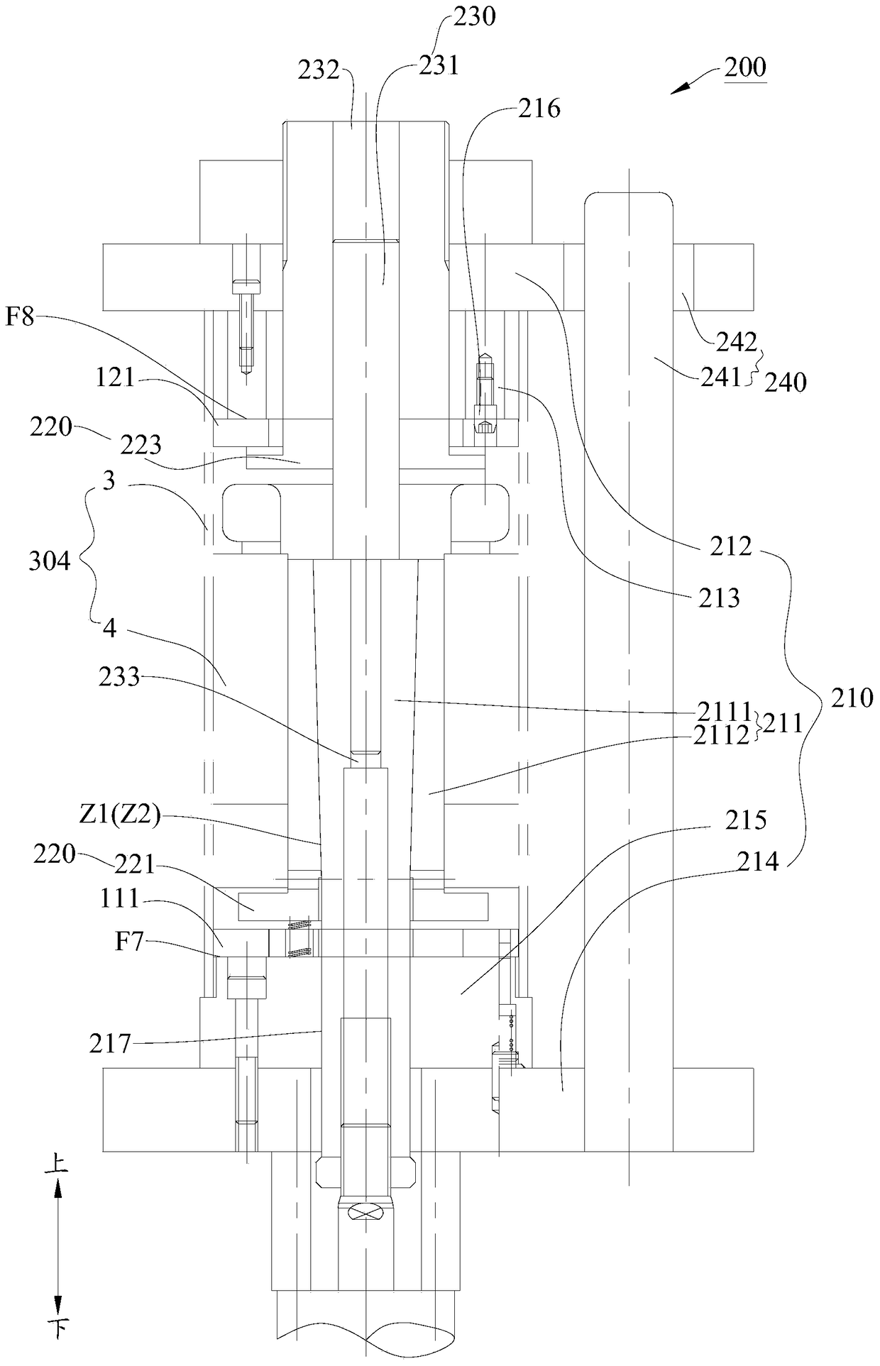
[0105] Such as image 3 As shown, the assembly method steps of the rotary compressor 100 in the first embodiment are as follows:

[0106] S1: respectively position the first frame 111 on the first positioning surface F7 of the lower positioning seat 214, position the second frame 121 on the second positioning surface F8 of the upper positioning seat 212, and position the housing stator assembly 304 Overcoat on the elastic sleeve 2112, and position the lower end surface of the middle housing 3 on the lower positioning seat 214;

[0107] S2: The clamping system 220 is working, wherein the upper clamp 223 on the upper positioning seat 212 moves upwards to clamp the second frame 121 on the upper positioning platform 213, and the upper rigid shaft 2111 of the lower positioning seat 214 moves downward , so as to press the stator inner diameter surface F5 of the housing stator assembly 304 tightly on the outer surface of the elastic sleeve 2112, and clamp the first frame 111 on the ...

Embodiment 2

[0112] Such as Figure 4 As shown, the assembly method steps of the rotary compressor 100 in the second embodiment are as follows:

[0113] S1: respectively position the first frame 111 on the first positioning surface F7 of the lower positioning seat 214, position the second frame 121 on the second positioning surface F8 of the upper positioning seat 212, and position the housing stator assembly 304 Overcoat on the elastic sleeve 2112, and position the lower end surface of the middle housing 3 on the lower positioning seat 214;

[0114] S2: The clamping system 220 works, the first rotary cylinder 222 clamps the first frame 111 on the lower positioning platform 215, and the second rotary cylinder 224 clamps the second frame 121 on the upper positioning platform 213, so that the second The first frame 111 and the second frame 121 are respectively clamped on the lower positioning seat 214 and the upper positioning seat 212; the rigid shaft 2111 moves toward the end where the cr...


PUM


Abstract

The invention discloses an assembly fixture of a rotation type compressor and an assembly method. The rotation type compressor comprises a first stand and a second stand, the two stands are fixed on the inner wall face of a compressor shell respectively, a main bearing, an accessory bearing or an air cylinder or a partition plate or parts of other compression components are fixed on the first stand, and the second stand is used for supporting the upper portion of a crank. The assembly fixture of the compressor comprises a locating system and a clamping system. The locating system comprises a fixing core component, an upper locating base and a lower locating base, the fixing core component is sleeved with a shell stator assembly part, a middle shell is clamped between the upper locating base and the lower locating base, a lower locating platform is arranged on the lower locating base and used for locating the first stand, and an upper locating platform is arranged on the upper locating base and used for locating the second stand. The clamping system is used for clamping the first stand and the second stand. By means of the assembly fixture, the assembly accuracy and cooperation uniformity between a stator and a rotor are guaranteed, the abrasion and noise between each bearing and the crank are made to be low, when the crank rotates, the torque power consumption is low, the motor clearance unbalance amount is little, and the small-clearance assembly is achieved.

Description

technical field [0001] The invention relates to the field of compressor processing equipment, in particular to an assembly tool and an assembly method of a rotary compressor. Background technique [0002] The compressor industry generally adopts the method of directly welding and fixing the compression components to the shell to fix the compression components to form the gap between the stator and rotor of the motor. However, due to the large number of assembly-related dimensions, dimensional interference often occurs between parts or between parts and fixtures during the assembly process. And because of the influence of welding stress, the gap between the stator and rotor of the motor after welding often changes, resulting in the deterioration of the gap imbalance of the motor and the decrease of the performance of the compressor. [0003] In order to solve the above problems, major compressor manufacturers and related research institutes have done a lot of work, among whi...

Claims


Application Information

Patent Timeline
Patent Type & Authority Patents(China)
IPC IPC(8): B23K31/02B23K37/04
CPCB23K31/02B23K37/0443
Inventor 徐利华马继飞王小峰刘文军
Owner GUANGDONG MEIZHI COMPRESSOR
Why Eureka
Try Eureka