High temperature rod member unloading conveyer

A conveying device, high temperature technology, applied in metal processing and other directions, can solve the problems of lack of, inability to meet the working range of robots, transformation, etc., to achieve the effect of convenient maintenance, improved automation production level, and high efficiency

A conveying device, high temperature technology, applied in metal processing and other directions, can solve the problems of lack of, inability to meet the working range of robots, transformation, etc., to achieve the effect of convenient maintenance, improved automation production level, and high efficiency

CN104959868AInactive Publication Date: 2015-10-07HEFEI UNIV OF TECH

Image

  • High temperature rod member unloading conveyer
  • High temperature rod member unloading conveyer
  • High temperature rod member unloading conveyer

Examples


Embodiment Construction

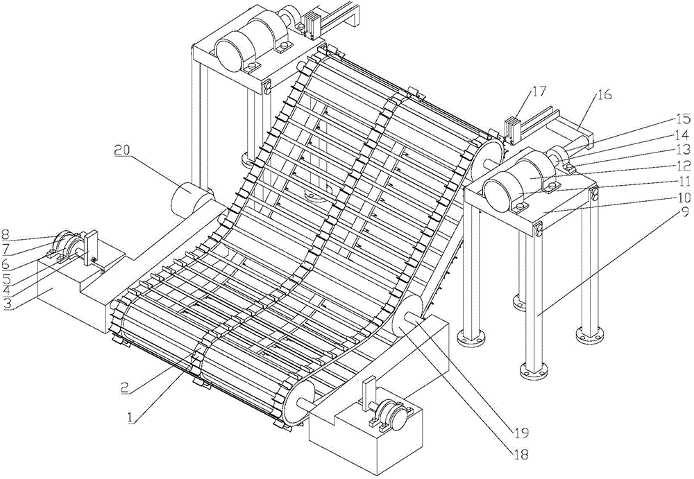
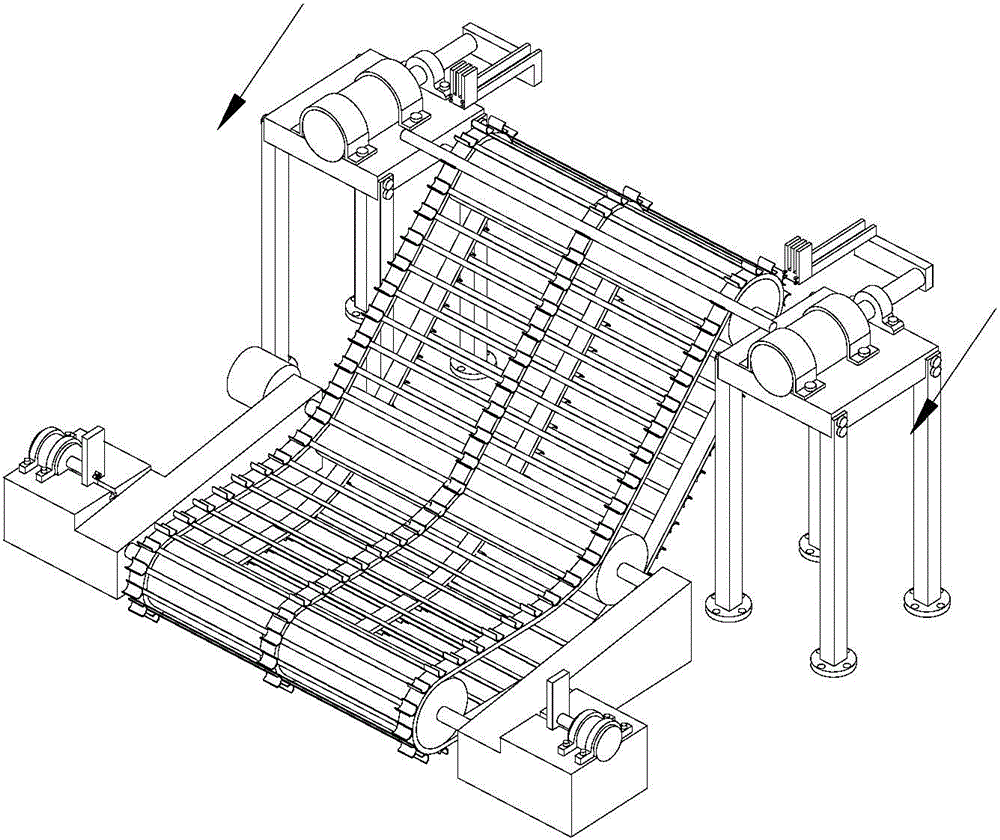
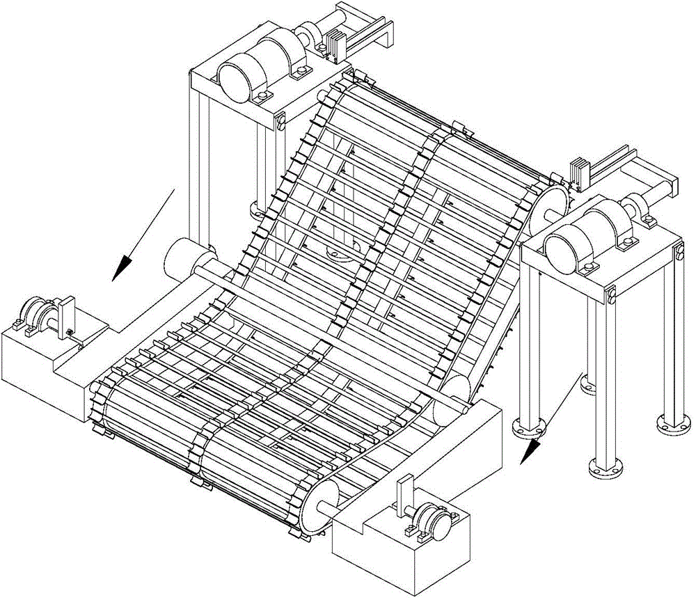
[0023] In this example, if figure 1 As shown, a high-temperature rod unloading transmission device includes: a high-temperature rod unloading mechanism responsible for taking out the heated high-temperature rod from the conveying line, responsible for conveying the rod taken out from the conveying line to a designated position The transmission mechanism for the industrial robot to transport to the next manipulator and the positioning mechanism responsible for axially positioning the high-temperature rod moving to the designated position, so that the industrial robot can accurately grab the rod and process it in the next process;

[0024] The high-temperature bar blanking mechanism includes two blanking mechanisms, and the two blanking mechanisms are respectively arranged on both sides of the transmission mechanism. Each blanking mechanism includes a base platform, a fixed frame 11, a hydraulic cylinder for blanking 12, and a positioning frame 15 , High temperature connecting r...


PUM


Abstract

The invention discloses a high temperature rod member unloading conveyer. The high temperature rod member unloading conveyer is characterized by comprising high temperature rod member unloading mechanisms, a conveying mechanism and a positioning mechanism. Each unloading mechanism comprises a pedestal, a fixing support, an unloading hydraulic cylinder, a positioning support, a high temperature connecting rod member and an unloading claw. The conveying mechanism comprises a driving sprocket, a driving chain, a discharge hook, two pedestals and a motor. Each positioning mechanism comprises a hydraulic cylinder fixing support, a positioning hydraulic cylinder and a positioning slide block. The high temperature rod member unloading conveyer can cooperate with a robot to automatically unload, the work efficiency can be raised, and the labor force can be saved.

Description

technical field [0001] The invention relates to a high-temperature rod automatic production line equipment, in particular to a high-temperature rod blanking and conveying device. Background technique [0002] With the advancement of science and technology, automated production lines are more and more widely used in factories, especially in auto parts manufacturers. Automated production lines can greatly improve production efficiency and product qualification rates. Therefore, more and more auto parts Component manufacturers have begun to automate traditional worker-dominated production lines, especially for processes with harsh processing environments such as thermoforming of automotive stabilizer bars. This demand has become particularly necessary. In the process of production line transformation, due to cost considerations, many manufacturers cannot completely transform the traditional production line. Therefore, the automated production line that needs to be transformed i...

Claims


Application Information

Patent Timeline
07 Oct 2015
Publication
CN104959868A
IPC
B23Q7/04; B23Q7/00
CPC
B23Q7/00; B23Q7/04
Inventors
黄康; 孙亚斌