An improved two-inlet concentration gradient generator and its design method

A technology of concentration gradient and generator, which is applied in the application field to achieve the effect of low requirements, improved accuracy and improved resolution

Active Publication Date: 2018-01-30
ZHEJIANG UNIV
View PDF3 Cites 0 Cited by
  • Summary
  • Abstract
  • Description
  • Claims
  • Application Information

AI Technical Summary

Problems solved by technology

These are common disadvantages of convective-type concentration gradient generators

Method used


Image

  • An improved two-inlet concentration gradient generator and its design method
  • An improved two-inlet concentration gradient generator and its design method
  • An improved two-inlet concentration gradient generator and its design method

Examples


Embodiment 1

[0031] Embodiment 1: quadratic function y=x 2 Design of Concentration Gradient Generator

[0032] (1) The objective function itself has been normalized, that is, f(x)=x 2 . Take the resolution as 0.5, then according to α=0.5≥max{f((j+1) / 2 N-1 )-f(j / 2 N-1 )}, get N≥4, take N=4, then there are 4 levels in total, and there are 8 splitter plates in the 4th level.

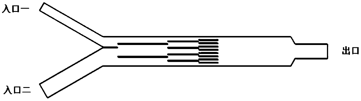
[0033] (2) The width of the main channel of the concentration gradient generator is 400 μm. According to the principle of uniform distribution of the final distribution plate, the distances between the 8 distribution plates of the fourth level and the wall of the main channel can be calculated as 44.4, 88.9, 133.3, 177.8, 222.2, 266.7, 311.1, and 355.6 μm.

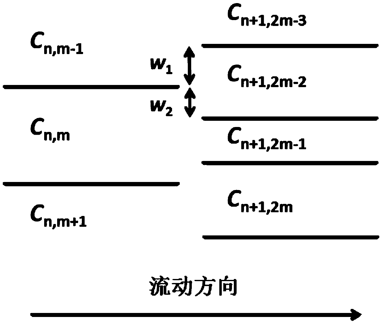
[0034] (3) According to C n,m =C n+1,2m-1 It can be seen that the concentration of the first channel of the third level C 3,1 =C 4,1 =f(0 / 2 3 )=0, the second channel concentration C 3,2 =C 4,3 =f(2 / 2 3 ) = 1 / 16. And the second channel concentration C o...

Embodiment 2

[0036] Embodiment 2: exponential function y=e 2x Design of Concentration Gradient Generator

[0037] (1) Normalize the objective function to f(x)=(e 2x -1) / (e 2 -1), take the resolution as 0.5, then according to α=0.5≥max{f((j+1) / 2 N-1 )-f(j / 2 N-1 )}, get N≥4, take N=4, then there are 4 levels in total, and there are 8 splitter plates in the 4th level.

[0038] (2) The width of the main channel of the concentration gradient generator is 400 μm. According to the principle of uniform distribution of the final distribution plate, the distances between the 8 distribution plates of the fourth stage and the wall of the main channel are calculated as 44.4, 88.9, 133.3, and 177.8, respectively. , 222.2, 266.7, 311.1 and 355.6 μm.

[0039] (3) According to C n,m =C n+1,2m-1 It can be seen that the concentration of the first channel of the third level C 3,1 =C 4,1 =f(0 / 2 3 )=0, the second channel concentration C 3,2 =C 4,3 =f(2 / 2 3 ) = 0.1015. And the second channel concen...

Embodiment 3

[0041] Embodiment 3: the preparation of two inlet concentration gradient generators

[0042] (1) Photolithography: Use AutoCAD to draw the microchannel pattern, then output the pattern to the film, and use standard photolithography technology to transfer the microchannel pattern to the silicon substrate template of SU-8 negative photoresist, and then forming a male mold patterned by microchannels;

[0043] (2) Pattern transfer: Mix the PDMS prepolymer and crosslinking agent evenly according to the mass ratio of 10:1, pour horizontally onto the SU-8 mold obtained by photolithography, put it in a vacuum box for 15 minutes to remove air bubbles, and then put Heat it in an oven at 70°C for 2 hours until it solidifies and take it out. Cut and peel off the PDMS, then use a hole punch to punch holes at the individual inlet and outlet channels;

[0044] (3) Bonding: The PDMS substrate with microstructure and the cleaned and dried glass cover slip are permanently bonded with a plasma...


PUM


Abstract

The invention discloses an improved two-inlet concentration gradient generator and a design method thereof. The concentration gradient generator is processed by a soft lithography method, and structurally comprises two inlets, one outlet, a main channel, and a series of splitter plates that are subjected to special structure design and parallel to the main channel. Repeated separation and mixing of a fluid can be realized through the splitter plates, so that a certain concentration gradient is set up at the downstream of the splitter plates. The finally formed concentration gradient is determined by the structural position of the splitter plates, and the concentration gradient resolution of the splitter plate outlets is determined by the series of the splitter plates, the more the series is, the higher the resolution is. The number of the splitter plates contained at each level increases exponentially. The concentration gradient generator can realize concentration gradient establishment of arbitrary monotonic function, and only needs two fluid inlets. The structure is compact, the generated concentration gradient is stable, and the concentration gradient generator can be used for microbial chemotaxis research, drug screening and other biology, pharmacy and medical engineering fields.

Description

technical field [0001] The invention relates to a microfluidic chip and its application fields such as biology, medicine, and pharmaceutical engineering, and in particular to a concentration gradient generation device based on microfluidic technology and a design method thereof. Background technique [0002] In cell biology research, drugs or biological factors have important effects on the behavior of cells. In order to study these behaviors in vitro, it is often necessary to establish a certain concentration gradient in the environment where the cells are located, for which a concentration gradient generating device is needed. Microfluidic systems are widely used in various in vitro studies of cells, and are small in scale, stable in flow and slow in molecular diffusion, suitable for maintaining a stable concentration gradient. Therefore, the concentration gradient generator based on microfluidic technology has attracted extensive attention from related industries. [00...

Claims


Application Information

Patent Timeline
Patent Type & Authority Patents(China)
IPC IPC(8): C12M3/00
CPCC12M23/16
Inventor 许忠斌黄兴崔赟
Owner ZHEJIANG UNIV
Why Eureka
Try Eureka