
Vacuum explosion chamber and contact structure thereof

A vacuum interrupter and contact technology, which is applied to circuit breaker contacts, high-voltage air circuit breakers, electrical components, etc. class, effect of increasing contact area and arcing area

Inactive Publication Date: 2015-10-07
BEIHANG UNIV
View PDF3 Cites 11 Cited by
  • Summary
  • Abstract
  • Description
  • Claims
  • Application Information

AI Technical Summary

Problems solved by technology

At present, the breaking of the vacuum arc is mainly concentrated on the power frequency AC. At first, the flat contact was used, but the breaking capacity could not meet the requirements, and the transverse magnetic and contact structures appeared one after another.

Method used


Image

  • Vacuum explosion chamber and contact structure thereof
  • Vacuum explosion chamber and contact structure thereof
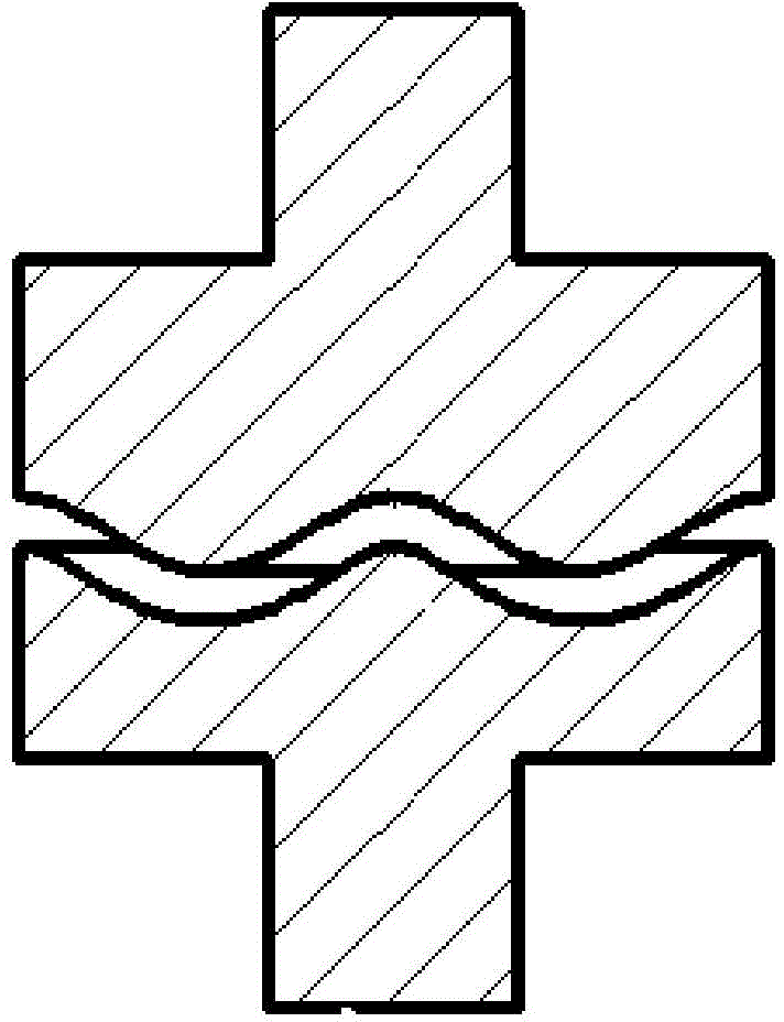
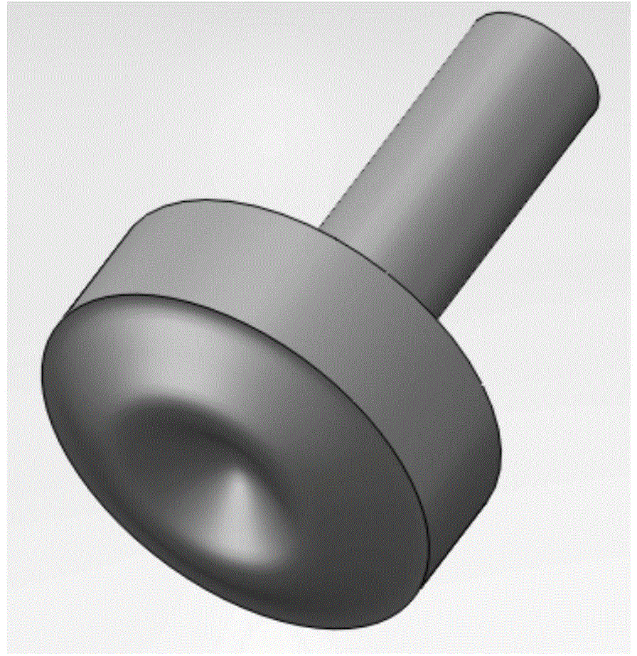
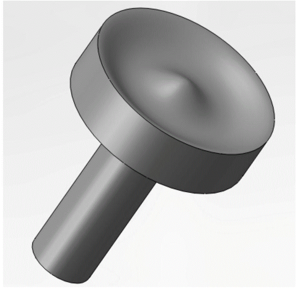
  • Vacuum explosion chamber and contact structure thereof

Examples


Embodiment Construction

[0021] The present invention will be described in further detail below through specific embodiments in conjunction with the accompanying drawings.

[0022] In order to improve the breaking capacity of the vacuum switch and reduce the volume of the vacuum interrupter, the invention provides a vacuum interrupter and its contact structure.

[0023] The contact structure for the vacuum interrupter includes: a cathode contact and an anode contact arranged oppositely, the end faces of the cathode contact and the end faces of the anode contact are curved surfaces corresponding to each other, and the end faces transition smoothly.

[0024] In the vacuum interrupter including the above-mentioned contact structure, the contact structure is covered with a shield, and the two ends are respectively connected to a moving conductive rod and a static conductive rod.

[0025] As an important component, the vacuum interrupter can form a vacuum circuit breaker.

[0026] In the contact structure...


PUM


Abstract

The invention relates to the vacuum circuit breaker technical field, more specifically a vacuum explosion chamber and a contact structure thereof. The contact structure comprises a cathode contact and an anode contact oppositely arranged; the end surface of the cathode contact and the end surface of the anode contact are curve revolution surfaces or curve straight surfaces mutually corresponding, and end surfaces transit smoothly. The contact structure can increase end surface contact areas, promote arcs to convert into a diffusion state, increase contacting areas of contacts, arcing areas and back-arc condensation remaining plasma and metal steam areas when a contact diameter is fixed, and furthermore improve a vacuum explosion chamber cut-off capability, and reduce a vacuum switch size.

Description

technical field [0001] The invention relates to the technical field of vacuum circuit breakers, in particular to a vacuum interrupter and its contact structure. Background technique [0002] The research on vacuum arc continuously promotes the development and progress of vacuum interrupter technology. At present, the breaking of the vacuum arc is mainly concentrated on the power frequency AC. At first, the flat contact was used, but the breaking capacity could not meet the requirements, and the transverse magnetic and contact structures appeared one after another. Typical longitudinal field contacts keep the vacuum arc stable and diffuse at high currents. Typical transverse magnetic field contacts include Archimedes spiral grooves, cup-shaped transverse magnets, swastikas, etc. Due to the spiral groove and the groove of the cup-shaped contact, the moving and static contacts are respectively equivalent to two current loops with opposite directions, and a radial radial magne...

Claims


Application Information

Patent Timeline
Patent Type & Authority Applications(China)
IPC IPC(8): H01H73/04H01H33/66H01H33/664H01H73/18
CPCH01H33/6646H01H33/66H01H73/04H01H73/18
Inventor 武建文霍文磊
Owner BEIHANG UNIV
Learn More