Omnidirectional antenna and omnidirectional antenna array
An omnidirectional antenna and array technology, applied in the field of omnidirectional antennas and omnidirectional antenna arrays, can solve the problem of small antenna gain bandwidth, and achieve the effects of improving market competitiveness, small Q value, and reducing out-of-roundness
- Summary
- Abstract
- Description
- Claims
- Application Information
AI Technical Summary
Problems solved by technology
Method used
Image

Examples
Embodiment 1
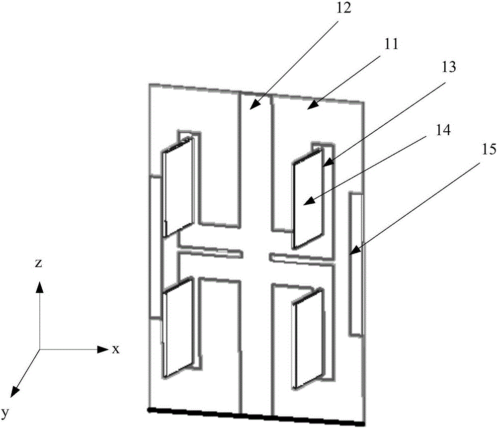
[0042] figure 1 is a schematic diagram of a surface of a dielectric substrate of an omnidirectional antenna according to an embodiment of the present invention, see figure 1 , the omnidirectional antenna in this embodiment of the present invention includes: a dielectric substrate 11 and a first omnidirectional radiation unit;
[0043] The first omnidirectional radiation unit includes: a main dipole, a parasitic dipole 15 and a metal base plate 12;
[0044] The main dipole includes: a first metal sheet 13 printed on a surface of the dielectric substrate 11 and a second metal sheet 14 perpendicular to the dielectric substrate 11 and inserted into the first metal sheet 13;
[0045] The first metal sheet 13, the parasitic dipole 15 and the metal base plate 12 are printed on one surface of the dielectric substrate 11, the first metal sheet 13 is printed in front of the metal base plate 12, and the parasitic dipole 15 is printed on the first metal sheet 13 ahead. The front here i...
Embodiment 2
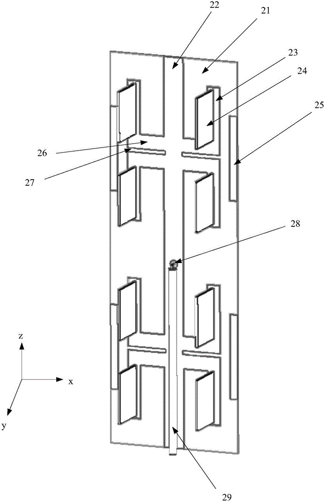
[0048] figure 2 is a schematic diagram of a surface of a dielectric substrate of an omnidirectional antenna according to another embodiment of the present invention, see figure 2, the omnidirectional antenna of the present invention also includes: a second omnidirectional radiation unit, the second omnidirectional radiation unit has the same structure as the first omnidirectional radiation unit, and the metal base plate of the second omnidirectional radiation unit is the same as the first omnidirectional radiation unit. The metal base plates of the radiating elements are connected together. That is, the second omnidirectional radiation unit also includes a metal base plate 22, a first metal sheet 23, a second metal sheet 24, and a parasitic dipole 25. The first metal sheet 23 and the second metal sheet 24 form the main dipole of the three-dimensional structure. The first metal sheet 23 is printed in front of the metal base plate 22 , and the parasitic dipole 25 is printed i...
Embodiment 3
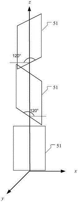
[0068] Figure 5 is a schematic diagram of an omnidirectional antenna array according to an embodiment of the present invention, see Figure 5 , the omnidirectional antenna array of the present invention includes: three omnidirectional antennas according to one aspect of the present invention;
[0069] The three omnidirectional antennas 51 form an antenna array on the vertical plane, and the included angle between two dielectric substrates of the three omnidirectional antennas 51 is 120°.
[0070]In specific applications, higher gain can be obtained by using the three omnidirectional antennas in the second embodiment to form an omnidirectional antenna array. When three omnidirectional antennas are formed in an array, the three omnidirectional antennas are rotated by 120 degrees in sequence. In the entire frequency band (1.65GHz–2.76GHz), the out-of-roundness of the horizontal plane pattern will be within 1dB. And in the case of ignoring the loss of the feeder cable and the p...
PUM
 Abstract
Description
Claims
Application Information
PatSnap Eureka turns technology decisions into work you can execute. Powered by our Innovation Knowledge Graph, it runs expert workflows across engineering, life sciences, materials and intellectual property. Get your review-ready output in minutes.


