Filtering amplification excitation PWM power supply based on logic protection emitter coupling mode

A technology of emitter coupling and logic protection, applied in the direction of adjusting electrical variables, electrical components, control/regulating systems, etc., can solve the problems of large ripple coefficient, low efficiency, radio frequency interference, etc., to achieve good filtering and amplification, output current Variation control range improves and reduces the effect of RF interference

Inactive Publication Date: 2015-10-07
CHENGDU LEIKEER SCI & TECH
View PDF3 Cites 2 Cited by
  • Summary
  • Abstract
  • Description
  • Claims
  • Application Information

AI Technical Summary

Problems solved by technology

[0004] The purpose of the present invention is to overcome the defects of large ripple coefficient, serious radio frequency interference, complex circuit and low efficiency existing in the current switch-type regulated power supply, and provide a filter-amplified excitation pulse width-adjustable power supply based on logic protection emitter coupling

Method used


Image

  • Filtering amplification excitation PWM power supply based on logic protection emitter coupling mode
  • Filtering amplification excitation PWM power supply based on logic protection emitter coupling mode
  • Filtering amplification excitation PWM power supply based on logic protection emitter coupling mode

Examples


Embodiment

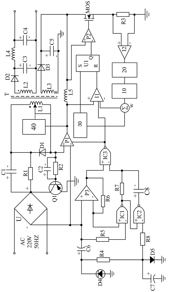
[0026] Such as figure 1 As shown, the present invention includes a diode rectifier U, a power amplifier P1, a transformer T, a switch filter circuit, a power supply output circuit, a voltage transformation feedback circuit, a switch control circuit, an oscillator, a current comparator I1, a current comparator I2, a slope compensation device W, sliding regulator, beam excitation logic amplifier circuit, filter amplifier circuit 10 and logic protection emitter coupled amplifier circuit 20. Wherein, the transformer T is composed of a primary coil L1 disposed on its primary side, a secondary coil L2 and a secondary coil L3 disposed on its secondary side. In the present invention, a sliding tap is provided on the primary coil L1 of the transformer T, and the sliding tap is controlled by a sliding regulator to ensure that the primary coil L1 and the primary coil of the transformer T can be adjusted according to the output result of the switch control circuit. The turns ratio betwee...


PUM


Abstract

The invention discloses a beam-excited pulse width modulation power supply based on a logic protection emitter-coupled mode. The beam-excited pulse width modulation power supply mainly includes a diode rectifier U, a power amplifier P1, a transformer T, a switching filtering circuit connected in series between the diode rectifier U and the power amplifier P1, a power output circuit connected with a secondary coil L2 of the transformer T, a transformation feedback circuit connected with a secondary coil L3 of the transformer T, a switching control circuit connected with the transformation feedback circuit, and the like. The beam-excited pulse width modulation power supply is characterized in that a logic protection emitter-coupled amplifying circuit is further connected in series between a slope compensator W and a current comparator I2. The beam-excited pulse width modulation power supply provided by the invention has the advantages that the slope compensator, a voltage comparator and the current comparator are innovatively utilized in a power circuit, so that the radio-frequency interference from the circuit and an external device is effectively reduced, and the circuit structure is greatly simplified to achieve much lower manufacture and maintenance costs.

Description

technical field [0001] The invention relates to a switching stabilized voltage power supply, in particular to a logic-protected emitter-coupling filter-amplified excitation pulse width-adjustable power supply. Background technique [0002] With the continuous advancement of science and technology, electronic products have brought great convenience to people's life while their functions are becoming more and more powerful. The voltage stabilizing circuit is easy to operate. The traditional series linear regulating voltage stabilizing circuit has the characteristics of high stability, adjustable output voltage, small ripple coefficient, and simple circuit. However, the adjustment tubes of these series linear adjustment type voltage regulator circuits always work in the amplified state, and current flows all the time, so the power consumption of the tubes is relatively large, and the efficiency of the circuit is not high, generally only reaching 30% to 50%. %about. In order t...

Claims


Application Information

Patent Timeline
Patent Type & Authority Applications(China)
IPC IPC(8): H02M7/217H02M3/335H02M1/14H02M1/44
CPCH02M1/44H02M3/33523
Inventor 黄涛
Owner CHENGDU LEIKEER SCI & TECH
Why Eureka
Try Eureka